YV180X_Ope_E.pdf - 第159页
5 -83 EPD8013110 Operation Chapter 5 5 Creating the PCB data 1. First select “ CONVEYOR WIDTH ” to adjust the conveyor width. The conveyor width input box appears, so enter the PCB width (mm). e 2. Press the emer gency s…
5
-82
EPD8013110
Operation
Chapter 5
5
Creating the PCB data
4.3 Adjust Assistant commands
This operation checks whether the parameter settings are correct. For
parameters which are unspecified, the optimal values can be obtained by
performing “VISION TEST” here. The following adjustment procedure is
explained for cases where the “Mark Type” parameter in the Mark Type
Info. sub-window is set to “Fiducial”.
1 Select the mark data.
Move the cursor to the data you want to check on the Mark Info.
screen.
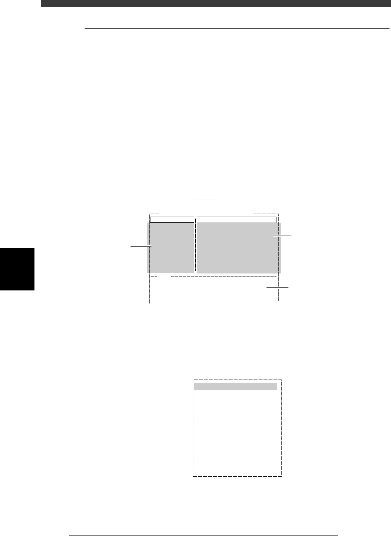
2 Open the Adjust Assistant screen.
Press the [F6] key to run the <2/1/B1 ADJUST ASSISTANT> command. The
Adjust Assistant screen appears as shown below.
Adjust assistant (mark) screen
27534-D8-00
Adjust Assist Items
Mark Threshold
Tolerance (%)
Search Area (mm)
Outer Light Level
Inner Light Level
Axial Light Level
IR Outer Level
IR Inner Level
127
30
4.00
Mark Name : FIDUCIAL
Standard
Standard
Standard
Standard
Standard
V180
Then, select "TEACH MARK".
Command
FIX PCB
TEACH MARK
VISION TEST
PARAM. SEARCH
*
*
CHK THRESHOLD
EXIT
Message and results are
displayed here.
Adjust
Assistant
commands
Parameters
specified in
Mark Info.
Name of selected mark
3 Clamp the PCB in place.
Run “FIX PCB” of the Adjust Assistant commands and select the conveyor
table. The conveyor unit menu box appears.
Conveyor unit menu box
27535-C0-00
LOCATE PIN
PUSH UP
PCB CLAMP
EDGE CLAMP
PUSH IN
MAIN STOPPER
ENT. STOPPER
EXIT STOPPER
CONV. MOTOR
CONV. WIDTH
PROGRAM PIN
RETURN
CONVEYOR UNIT (STS.)
OFF
OFF
OFF
OFF
OFF
OFF
OFF
OFF
OFF
OFF
5
-83
EPD8013110
Operation
Chapter 5
5
Creating the PCB data
1. First select “CONVEYOR WIDTH” to adjust the conveyor width.
The conveyor width input box appears, so enter the PCB width (mm).
e
2. Press the emergency stop button and clamp the PCB on the conveyor
according to the selected PCB clamping method.
Reference
For details on the procedure for clamping the PCB on the conveyor, refer to “5. Clamping
the PCB” in this chapter and “8. Changing the conveyor unit setup” in Chapter 4.
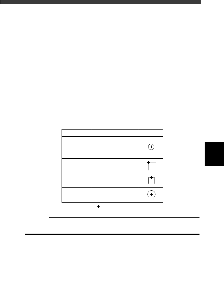
4 Perform teaching for the mark.
When the cross cursor in the center of the vision monitor is aligned with
the appropriate position in the mark (see the table below), skip this
step. If not, perform teaching as follows.
1. Run the TEACH MARK command.
2. Manipulate the joystick so that the cross cursor on the vision monitor is
aligned with the appropriate position in the mark (see the table below),
then press the [ENTER] key.
Mark teaching
25515-C0-00
Shape Type Teaching point Example
Circle
Square
Triangle
Sp. Shape
Center of mark
Corner of mark
Center of a square
edge line
Center of a round edge
Corner
TopEdge
CirEdge
:Cross cursor at center of screen
w
WARNING
STAY OUTSIDE THE MOVEMENT RANGE OF THE HEAD ASSEMBLY WHEN
YOU MANIPULATE THE YPU JOYSTICK.
5
-84
EPD8013110
Operation
Chapter 5
5
Creating the PCB data
5 Run the VISION TEST command.
Repeat this test several times. When no errors occur, the parameter settings
are appropriate. Advance to the next step. If an error occurs, adjust the
parameters with the procedure below.
1. Return to the Mark Info. screen with the EXIT command, and check that
the following parameters are set correctly.
Mark Type and MarkOutSize in the Mark Type Info. sub-
window
Shape Type and Surface Type in the Vision Info. sub-window
2. After checking the parameters, press the [F6] key to open the Adjust
Assistant screen again, then repeat Steps 4 to 5.
When no errors occur, move to the next step.
3. If an error still occurs, run the PARAM SEARCH command to find an
optimum threshold level.
4. After the optimum threshold level has been found, run “VISION TEST”
again.
When no errors occur, go to the next step.
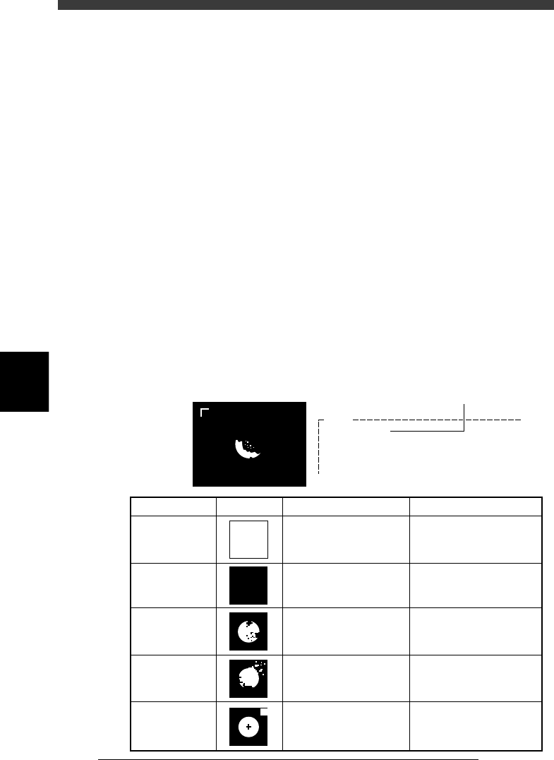
If the optimum threshold level could not be obtained, run the CHK
THRESHOLD command.
A binary image will be displayed on the vision monitor according to
the current parameter settings as shown below. Adjust the threshold
level as suggested below, so that the mark image is clearly displayed.
Binary image (mark)
23534-C0-00
V192
(LEVEL=150)
Binary image is on the monitor......
[INS] or [DEL] key to change the threshold.
Hit [ENTER] to finish.
Current threshold setting
State
All white
All black
Noise within
mark
Noise outside
of mark
Other than
mark in
search area
Image Countermeasure
Increase the Mark
Threshold level with the
[INS] key.
Decrease the Mark
Threshold level with the
[DEL] key.
Increase the Cut Inner
Noise level in the Adjust
Assistant.
Increase the Cut Outer
Noise level in the Vision
Info. sub-window.
Decrease the Search
Area level in the Vision
Info. sub-window.
Remarks
Adjust it till the mark is
displayed.
Adjust it till the mark is
displayed.
Refer to "Search Area"
explained previously.
Recognition time becomes
longer as the Cut Inner
Noise level is increased.
Recognition time becomes
longer as the Cut Outer
Noise level is increased.