YV180X_Ope_E.pdf - 第246页
6 -11 EPD8013110 Operation Chapter 6 6 Using various functions 5 Set the “ FEEDER SET CONDITION ” parameter . Set this parameter to “ NO ” when performing only the block conversion. Refer to “ 9.2 Setting optimization co…
6
-10
EPD8013110
Operation
Chapter 6
6
Using various functions
2.2.1 Executing the block conversion
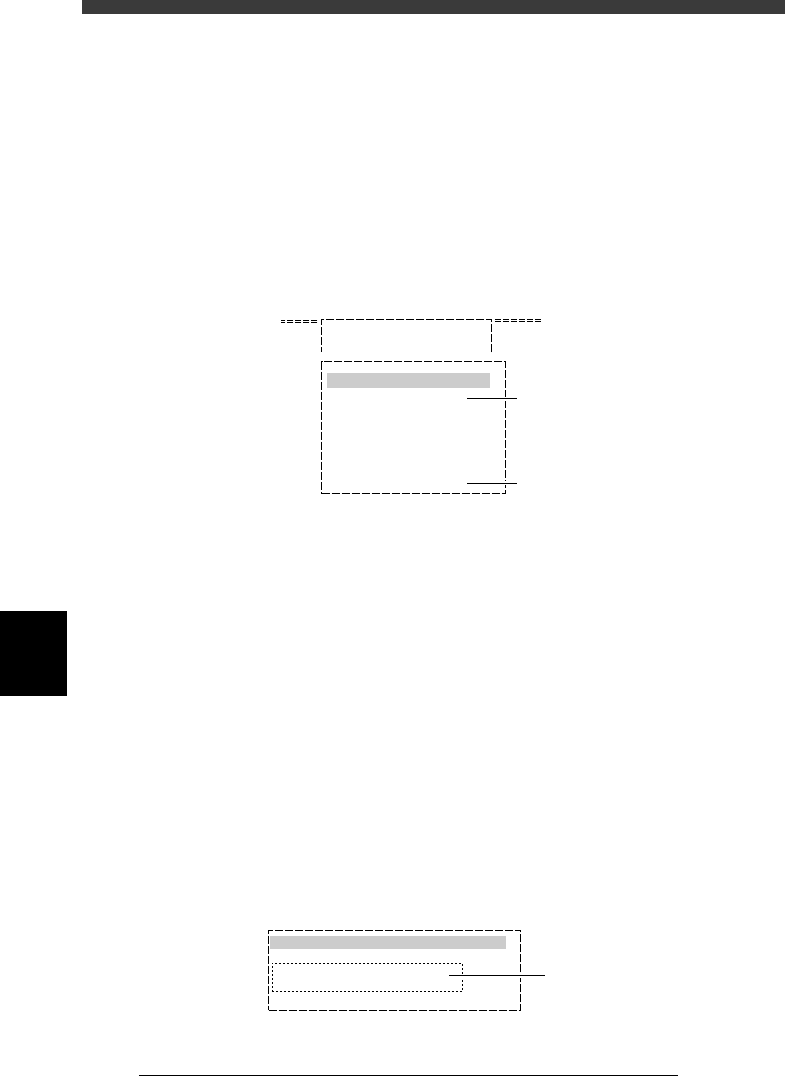
1 Select <2/2/A1 OBJECT SELECTION> and press the [EN-
TER] key.
The OBJECT SELECTION menu box then appears, along with the box
showing the initial settings for data generator.
2 Execute the PCB SELECTION command and select the PCB
name.
When a list of the registered PCB names appears, select the PCB to
execute block conversion, then select “QUIT” and press the [ENTER] key.
OBJECT SELECTION menu box in DATA_GENERATOR mode
27604-C0-00
A/ SETTING & RUN
A1 OBJECT SELECTION
OBJECT SELECTION
PCB SELECTION
FIXED PCB SELECTION
FIXED COMP. SEL.
LOAD LAST SELECTION
QUIT
Use this command
to select the PCB.
Execute this command
after selecting the PCB.
3 Select <2/2/A4 CONDITION SETTING> and press the
[ENTER] key.
The DATA GENERATOR CONDITION menu box then appears.
4 Select “BLOCK CONVERSION CONDITION” to set the
conditions.
The submenu box then appears, so line up the cursor with “1: CONV.
WITH NOTE DATA” or “2: CONV. WITHOUT NOTE DATA” and press the
[ENTER] key, while referring to the description below.
1: CONV. WITH NOTE DATA :
Block repeat data is converted into data for a single PCB with the
original data still remaining. In this case, the single PCB data can be
reconverted back into the original block data.
2: CONV. WITHOUT NOTE DATA :
Block repeat data is converted into data for a single PCB data,
without the original data remaining. The single PCB data cannot be
reconverted back into the block data.
BLOCK CONVERSION COND. setting box
27605-C0-00
0: NO
1: CONV. WITH NOTE DATA
2: CONV. WITHOUT NOTE DATA
3: CONV. BACK TO BLOCK
BLOCK CONVERSION CONDITION
Select either of these
conditions.
6
-11
EPD8013110
Operation
Chapter 6
6
Using various functions
5 Set the “FEEDER SET CONDITION” parameter.
Set this parameter to “NO” when performing only the block conversion.
Refer to “9.2 Setting optimization conditions” in Chapter 5 for more
details.
6 Execute the block conversion.
Press the [ESC] key to return to the <2/2/A/SETTING_&_RUN> menu
window, then select <2/2/A5 EXECUTE> and press the [ENTER] key. Block
conversion now starts.
7 Quit the command and save the data.
When block conversion is complete, press the [ESC] key to quit the current
command, then select <2/2/B5 RENAME & EXIT> and press the [ENTER]
key. Follow the message displayed on the screen to save the data.
Reference
When you want to save the data by overwriting the original data (when not necessary to
keep the original data), select <2/2/B0 SAVE & EXIT> and press the [ENTER] key.
n
Note
When block conversion is executed with the “BLOCK CONVERSION COND.” parameter
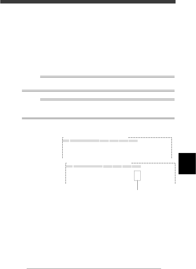
set to “1: CONV. WITH NOTE DATA”, the original block repeat data remains as “Note”
data.
Blk Repeat Info. screen after block conversion
27606-C0-00
No.
1
2
3
4
5
X
0.00
30.00
0.00
30.00
Y
0.00
0.00
50.00
50.00
Block Comment
BLOCK_1
BLOCK_2
BLOCK_3
BLOCK_4
Skip?
Exec
Exec
Exec
Exec
R
0.00
0.00
180.00
180.00
OBJ : Blk Repeat Info.PCB :
No.
1
2
3
4
5
X
0.00
30.00
0.00
30.00
Y
0.00
0.00
50.00
50.00
Block Comment
BLOCK_1
BLOCK_2
BLOCK_3
BLOCK_4
Skip?
Exec
Note
Note
Note
R
0.00
0.00
180.00
180.00
OBJ : Blk Repeat Info.PCB :
Before block conversion
Block repeat data remains as “Note” data.
After block conversion
6
-12
EPD8013110
Operation
Chapter 6
6
Using various functions
2.2.2 Reconverting to the block repeat data
When editing or correcting one-block PCB data which was converted from
block repeat data, it will prove convenient to use the original block repeat
data. This section explains how to reconvert such data into the original
block repeat data. This data reconversion is possible only when the block
conversion was executed under “1: CONV. WITH NOTE DATA”.
1 Select <2/2/A1 OBJECT SELECTION> and press the [EN-
TER] key.
The OBJECT SELECTION menu box then appears.
2 Execute the PCB SELECTION command and select the PCB
name.
When a list of the registered PCB names appears, select the PCB to
execute reconversion, then select “QUIT” and press the [ENTER] key.
3 Select <2/2/A4 CONDITION SETTING> and press the
[ENTER] key.
The DATA GENERATOR CONDITION menu box then appears.
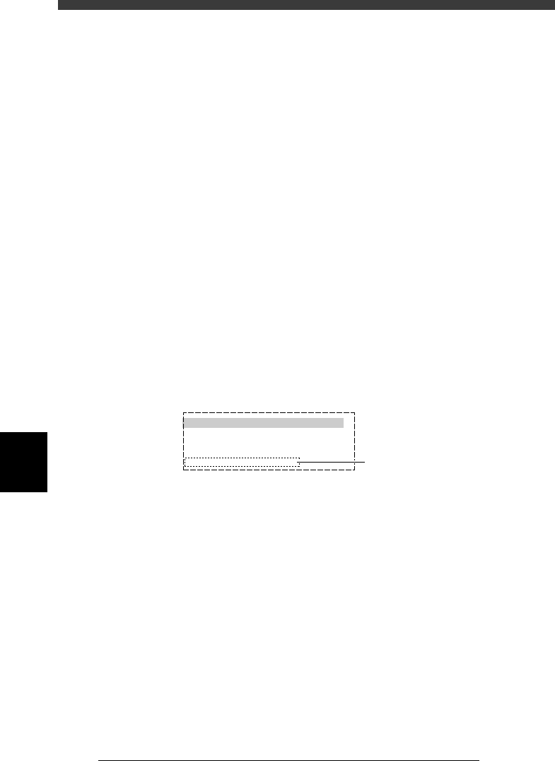
4 Select “BLOCK CONVERSION CONDITION” to set the
conditions.
When the submenu box appears, line up the cursor with “3: CONV. BACK
TO BLOCK” and press the [ENTER] key.
BLOCK CONVERSION CONDITION menu box
27607-C0-00
0: NO
1: CONV. WITH NOTE DATA
2: CONV. WITHOUT NOTE DATA
3: CONV. BACK TO BLOCK
BLOCK CONVERSION CONDITION
Move the cursor to this item
and press the [ENTER] key.
5 Set the “FEEDER SET CONDITION” parameter.
Set this parameter to “NO” when performing only the block reconversion.
Refer to “9.2 Setting optimization conditions” in Chapter 5 for more
details.
6 Execute the reconversion.
Press the [ESC] key to return to the <2/2/A/SETTING_&_RUN> menu
window, then select <2/2/A5 EXECUTE> and press the [ENTER] key. The
reconversion now starts.