YV180X_Ope_E.pdf - 第14页
1 -4 EPD8013110 Operation Chapter 1 1 Par t names and functions 2. Head assembly The head assemblies of the YV180X are mounted on the front and rear of the X arm. When vie wed from the front of the machine, the front is …
1
-3
EPD8013110
Operation
Chapter 1
1
Part names and functions
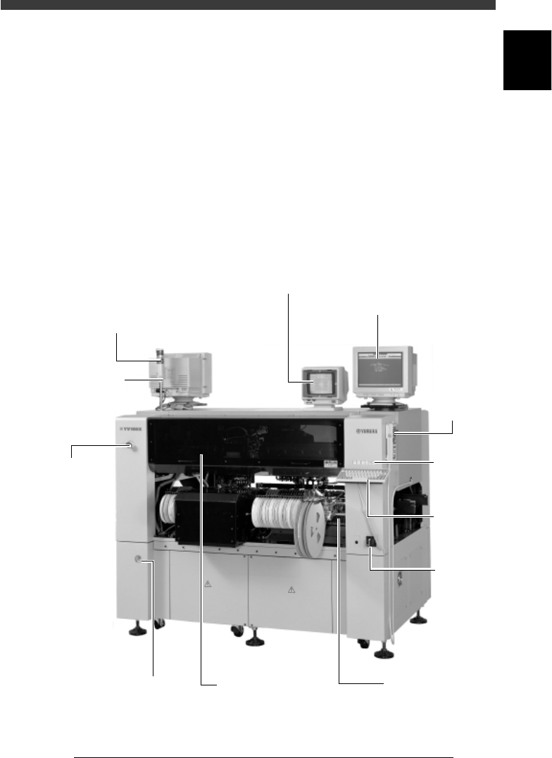
1. Main unit
A standard machine after installation is complete has the following con-
figurations. Names and functions of major parts of the main unit are
illustrated below.
Main unit
28101-D8-00
Warning lamp
Indicates current operating conditions
of the mounter in green, yellow and
red as follows.
Green: The machine is in automatic
operation.
Yellow: An error (return-to-origin
not performed, pickup error,
recognition error, etc.) or
interlock has occurred.
Red: The machine is
in emergency stop.
(Emergency stop
button on the machine
or YPU was pressed.)
Emergency stop
button
Pressing this button
immediately triggers
emergency stop.
This machine has
three emergency
stop buttons:
one each on the
left side at the front
of the machine and
on the right side
at the rear,
and the YPU.
Main
power
switch
Vision display
(vision monitor)
Displays an image taken
by the moving camera
or vision camera such as
recognition status of
a component and mark.
Operation display
(operation monitor)
Displays the VIOS software
screen on which the
machine can be operated.
If an error or problem occurs
during operation, a corre-
sponding message also
appears on this screen.
Safety cover
This cover must be closed
during operation. If opened,
emergency stop is triggered.
Keyboard
See "5.2"
in this
chapter.
YPU
See "5.1"
in this
chapter.
Feeder plate
See "3. Feeder plate"
in this chapter.
Pressure indicator
Shows supply air
pressure and pressure
drop detection
setting.
Alarm buzzer
This buzzer sounds
if an error or abnormal
operation occurs.
Operation
panel keys
See "5.3"
in this
chapter.
1
-4
EPD8013110
Operation
Chapter 1
1
Part names and functions
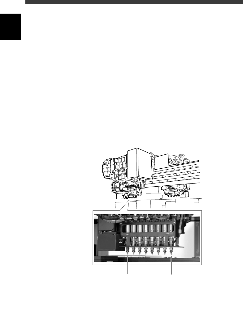
2. Head assembly
The head assemblies of the YV180X are mounted on the front and rear of
the X arm. When viewed from the front of the machine, the front is called
the A-table head assembly, and the rear the B-table head assembly.
2.1 Component pickup/mount head
Each head assembly of the YV180X has 8 in-line heads (nozzles). Head
numbers are designated from 1 to 8, from the right as viewed from the
front of each head assembly. The spacing of adjacent nozzles attached to
the head assembly is 16mm, which is identical to the pitch of the feeder
installation holes on the feeder plates.
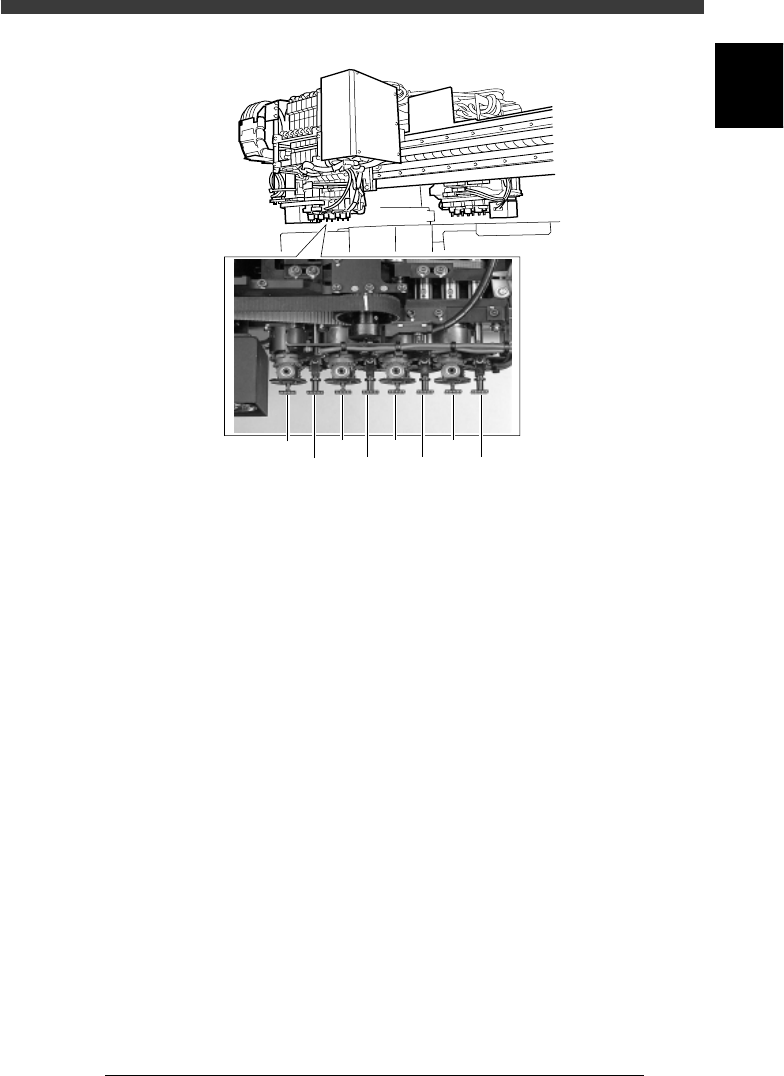
Optional flying nozzle change (FNC) functions can be installed to Heads 2,
4, 6 and 8. The FNC functions allow exchanging the nozzle at high speeds
while the head assembly is moving to a component feeder.
YV180X head assembly (standard head)
23101-D8-00
. . . . Head 1Head 8 . . .
1
-5
EPD8013110
Operation
Chapter 1
1
Part names and functions
YV180X head assembly with FNC (option)
23102-D8-00
2 4 6
Head 17 35
Head 8
Heads 2, 4, 6, 8 = FNC