YV180X_Ope_E.pdf - 第297页
6 -62 EPD8013110 Operation Chapter 6 6 Using various functions 6 7 T each the center of the pattern. 1. Following the message “ Please teach the template center . (Step 2) ” , align the center of the window (template) wi…
6
-61
EPD8013110
Operation
Chapter 6
6
Using various functions
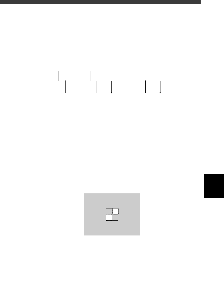
Upper left corner start (stationary) point:
The window can be enlarged or reduced with the arrow keys, using
the upper left corner of the window as a start point. However, the
window cannot be expanded further left or upwards of the start
point.
Center:
The entire window moves with the arrow keys.
Changing the window size and position
23625-C0-00
Moving point
Moving point Start (stationary) point
Start (stationary) point
Entire window moves
Arrow keys
When the lower right or upper left start point is selected, pressing an
arrow key changes the window size. When the center point is selected,
pressing an arrow key moves the entire window. If you press an arrow
key while holding down the [SHIFT] key, the entire window moves to
larger distance.
[ESC] key
Press the [ESC] key if you want to cancel pattern registration.
[ENTER] key
Press the [ENTER] key when the pattern size and position have been
determined, and advance to the next step.
Pattern size adjustment
23626-C0-00
X.Y:134.181
Size
Off
:
:
150.
127.
147
73
6
-62
EPD8013110
Operation
Chapter 6
6
Using various functions
6
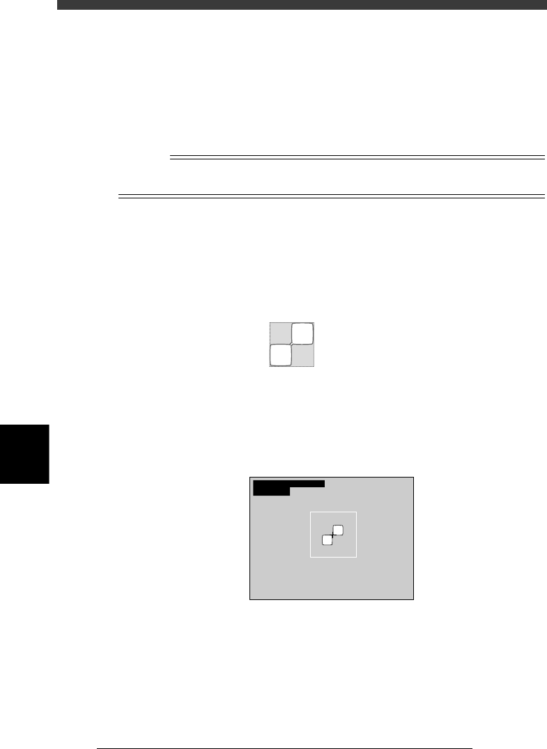
7 Teach the center of the pattern.
1. Following the message “Please teach the template center. (Step 2)”,
align the center of the window (template) with the center of the pattern
and then press the [ENTER] key. If they are already aligned, just press
the [ENTER] key.
2. The message “Do you want to save this template?” then appears. Press
the [ENTER] again to save the pattern. If you do not want to save it,
press the [ESC] key.
Reference
If the pattern size is too large, a “template size error” may occur. In this case, redo the
procedure from Step 6.
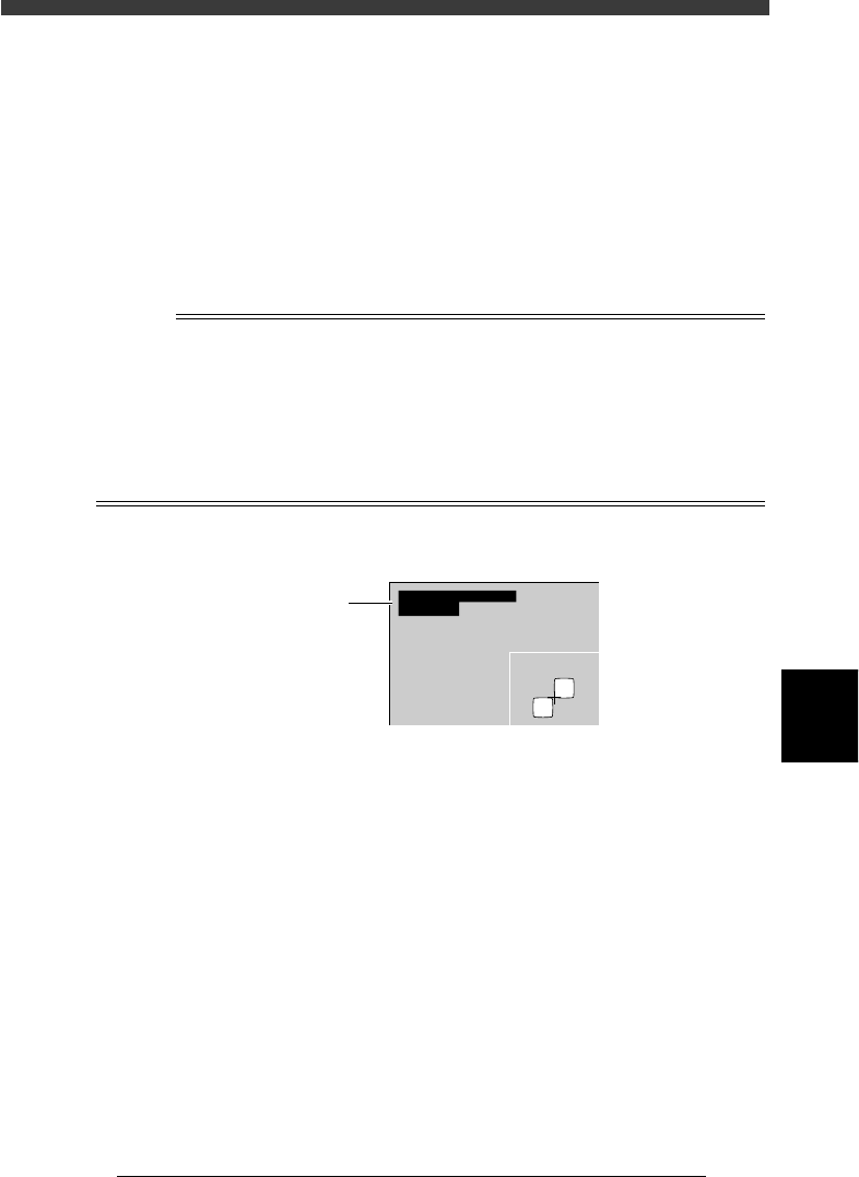
8 Check the image.
Execute the DISP. PATTERN command when registration is complete. The
image of the pattern enclosed by the window is displayed on the upper left
of the vision monitor. If an acceptable image cannot be obtained, redo the
procedure from Step 6.
Pattern display
21602-C0-00
Size
Offset
FileSize
:
:
:
190,
95.0
17322
147
74.0
9 Execute the VISION TEST command.
Check that the pattern is correctly recognized by executing the VISION
TEST command. Repeat this test several times. If the pattern can be
reliably detected, then the setting is okay.
VISION TEST screen for mark recognition
21603-C0-00
XC
mat
:
:
256.1
1.00
YC:255.9
6
-63
EPD8013110
Operation
Chapter 6
6
Using various functions
0 Check or set the adjust assistant items.
All values are entered automatically when the SAVE PATTERN command is
executed, except for “Tolerance” and “Search Area”. Complete entry of the
parameters in the Adjust Assist Items window by referring to the following
explanation.
Tolerance
Enter the percent of error tolerance during mark recognition. The
optimum value for pattern matching can be calculated as follows.
Tolerance = 1.00 - (“mat” value) x 100
where the “mat” value is the figure displayed on the upper left of the
vision monitor during measurement with the VISION TEST command.
n
NOTE
The “mat” value is a relative value showing how accurately the pattern being recognized
matches the pattern registered as the template. A value of “1.00” means that the pattern
matches the template by 100%. The lower the “mat” value, the lower the extent of
matching. In most cases, when you execute VISION TEST for the PCB which was used for
registering the pattern, the “mat” value will be 100%. To obtain a more accurate “mat”
value, we recommend executing VISION TEST for a few PCBs of the same type and
figuring out the average of the “mat” values. For detailed information about “Tolerance”,
refer to “4.2 Various parameter settings” in Chapter 5.
VISION TEST screen for mark recognition
23627-C0-00
XC
mat
:
:
256.1
1.00
YC:255.9
“mat” value
Search Area
Specify the size of the square (length of one side) used to search for the
pattern. A search is made within the square centered on the X-Y
coordinates of the pattern. We recommend specifying the square size
(search area) as wide as possible with no other marks present (resist
patterns, printed marks, etc.). If the search area is set too small (nearly
adjacent to the patterns), part of the patterns might be outside the search
area if position deviations occur due to clamping of the PCB. This
results in recognition errors.