YV180X_Ope_E.pdf - 第122页
5 -46 EPD8008100 Operation Chapter 5 5 Creating the PCB data 3.5.2 BGA components (BGA setting) BGA components are registered with the parameters shown below when the AlignmentT ype parameter is set to “ BGA ” . W ith th…
5
-45
EPD8008100
Operation
Chapter 5
5
Creating the PCB data
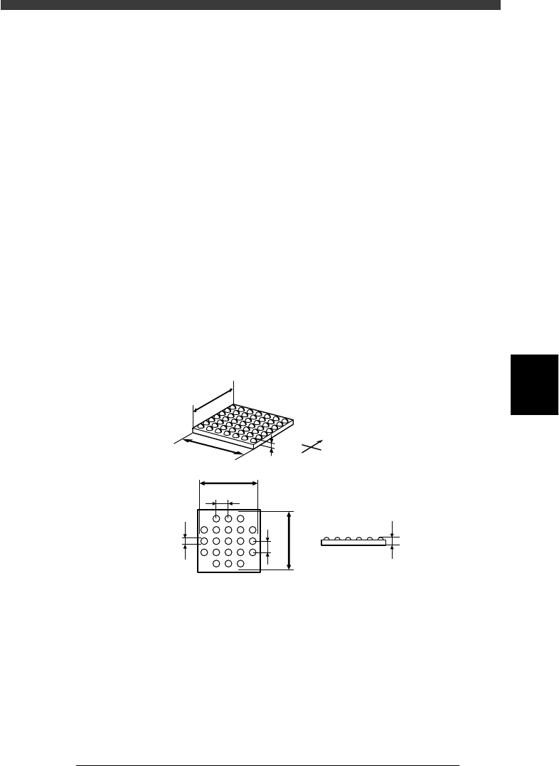
6. SHAPE INFO. parameters
When “Alignment Type” in the VISION INFO. sub-window is set to
“Simple BGA”, the following parameters are displayed in the SHAPE
INFO. sub-window.
61. Body Size X, Body Size Y
Enter the correct dimensions measured with a vernier caliper or microme-
ter.
62. Body Size Z
Enter the correct diameter measured with a vernier caliper or micrometer.
63. Dot number N, Dot number E
Enter the number of ball terminals arrayed in the N and E directions. If the
number of terminals per array differs from each other, enter the largest
number of terminals per array.
64. BGA diameter
Enter the diameter of ball terminals.
65. BGA pitch
Enter the spacing between ball terminals.
66. Dot amount
Enter the total number of ball terminals of the BGA component.
SHAPE INFO. parameters for BGA component
23515-C0-00
N
S
E
W
B
A
C
D
E
F
H
G
C
A : Body Size X
B : Body Size Y
C : Body Size Z
D : Dot number N
E : Dot number E
F : BGA pitch N
G : BGA pitch E
H : BGA diamete
r
Side view
Bottom view
5
-46
EPD8008100
Operation
Chapter 5
5
Creating the PCB data
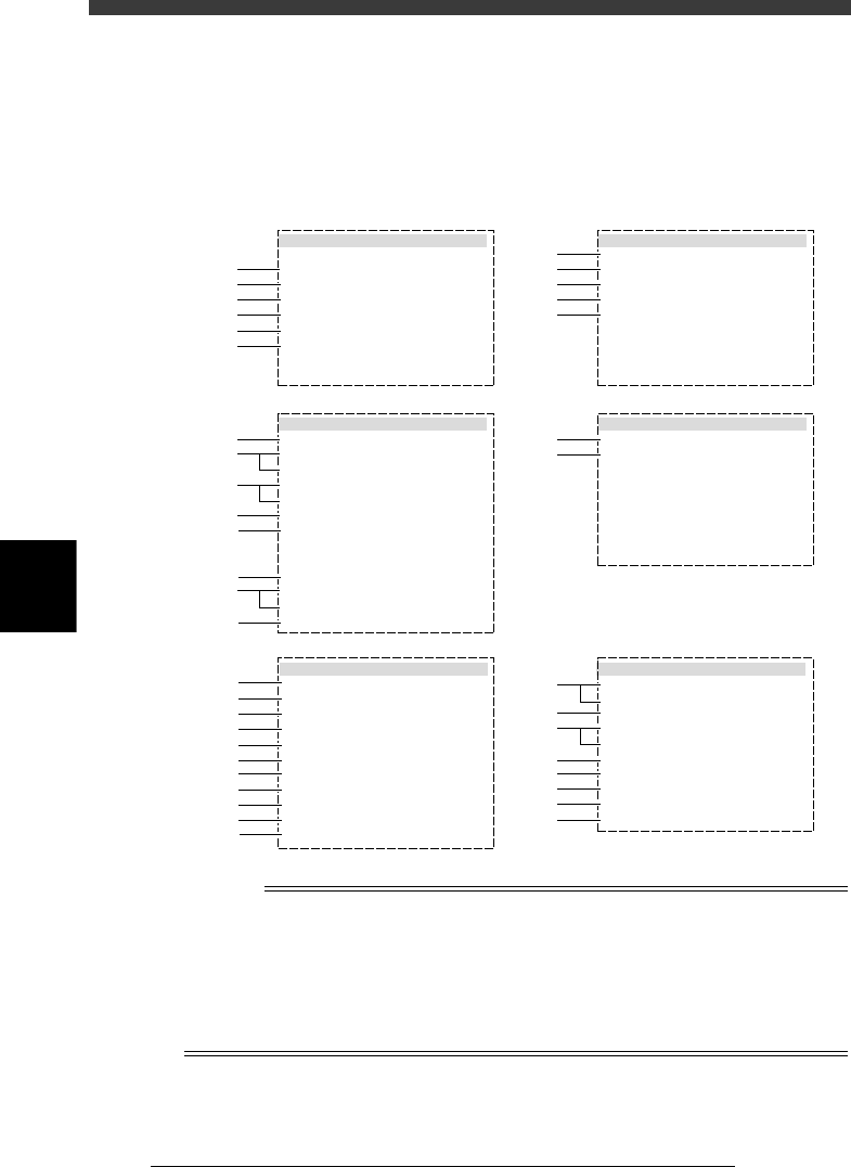
3.5.2 BGA components (BGA setting)
BGA components are registered with the parameters shown below when
the AlignmentType parameter is set to “BGA”. With this setting, the BGA
arrangement and nicked leads can bet checked.
BGA component parameters (when AlignmentModule is set to “BGA”)
27516-D8-00
6.SHAPE INFO.
Body Size X
Body Size Y
Body Size Z
Dot number N
Dot number E
BGA diameter
BGA pitch N
BGA pitch E
Dot amount
Binary Level
:
:
:
:
:
:
:
:
:
:
23.00
23.00
1.80
13
13
0.75
1.50
1.50
169
0
5.VISION INFO.
Alignment Group
Alignment Type
AlignmentModule
Light Selection
Lighting Level
Comp. Threshold
Comp. Tolerance
Search Area mm
Datum Angle
Comp. Intensity
MultiCam. Marker
:
:
:
:
:
:
:
:
:
:
:
Ball
BGA
Fore
Main + Coax
4/8
Non effective
Normal
NotUse
30
1.50
0
1.BASIC INFO.
Database No.
Comp. Package
Feeder Type
Required Nozzle
Feeder Set No.
Pos. Definition
Feeder Pos_X mm
:
:
:
:
:
:
:
Tape
32mmEmboss
ForQFP30mm 74
Teaching
950
7
-16.00
2.OPTION INFO.
FixCmpRef.
AIt.Cmp
Use feeder opt.
Comp. Group No.
Correct Pickpos
:
:
:
:
:
Yes
Not Use
0
0
0
3.PICK AND MOUNT INFO.
Pick Angle deg
Pick Timer
Mount Timer
Mnt Height
Pick Sequence
Mount Action
Mount Speed
PickupSpeed
XY Speed
Vacuum Check
Pick Vacuum
Mount Vacuum
Conv. Y Speed
:
:
:
:
:
:
:
:
:
:
:
:
:
4.DUMP INFO.
Dump Way
Retry Times
:
:
Dump POS
2
s
s
mm
%
%
%
%
%
0
0.30
0.20
Normal
QFP
30
100
100
SPECIAL CHK
FAST
0.0
10
10
mm
mm
mm
mm
mm
mm
1
2
3
4
5
6
41
42
43
44
45
46
47
48
49
50
51
11
12
13
14
15
31
32
61
62
63
64
64
65
66
67
21
22
23
24
25
26
27
28
n
NOTE
When setting the parameters shown in the sub-windows above, use the number keys to set
the parameters aligned on the right, while using the [INS], [DEL] or [Space] key to set
the parameters aligned on the left. However, there are some parameters which should be
set or optimized with the Adjust Assistant commands described later in “3.7” in this
chapter.
The displayed parameters differ slightly depending on the <3/1/A1 OPTION CONFIG>
settings.

5
-47
EPD8008100
Operation
Chapter 5
5
Creating the PCB data
1. BASIC INFO. parameters
1. Comp. Package
Refer to the description in “3.3.1 Standard chip components”.
2. Feeder Type
Refer to the description in “3.3.1 Standard chip components”.
3. Required Nozzle
Select the optimum nozzle that matches the component size from among
the nozzle types for QFP components. (See “Nozzle table” listed in
Supplement in this manual.)
4. Feeder Set No.
Refer to the description in “3.3.1 Standard chip components”.
5. Pos. Definition
Refer to the description in “3.3.1 Standard chip components”.
6. Feeder Pos_X
Refer to the description in “3.3.1 Standard chip components”.
2. OPTION INFO. parameters
For descriptions of the following OPTION INFO. parameters, refer to
“3.3.1 Standard chip components” in this chapter.
11. FixCmpRef.
12. Alt. Comp.
13. Use feeder opt.
14. Comp. Group No.
15. Correct Pickpos.
3. PICK & MOUNT INFO. parameters
21. Pick Angle deg
Use the same setting as for QFP components.
22. Pick Timer, Mount Timer
Refer to the description in “3.4.2 SOP component”.
23. Pick Height, Mount Height
Refer to the description in “3.3.1 Standard chip components”.
24. Pick Sequence
Refer to the description in “3.3.1 Standard chip components”.
25. Mount Action
Set this parameter to “QFP” when mounting accuracy is more important
than operation speed. (Refer to the description in “3.3.4 QFP components”
for detail.)
26. Vacuum Check
Set this parameter to “SPECIAL CHK” in most cases. (Refer to the
description in “3.3.4 QFP components” for detail. )