YV180X_Ope_E.pdf - 第71页
4 -32 4 Operation Chapter 4 4 Daily operation EPD8013110 8.5 T ransfer hook The transfer hook located under the X-axis arm transfers the PCBs between the carry-in con ve yor , A/B tables and carry-out conve yor . When ch…
4
-31
Operation
Chapter 4
4
Daily operation
EPD8013110
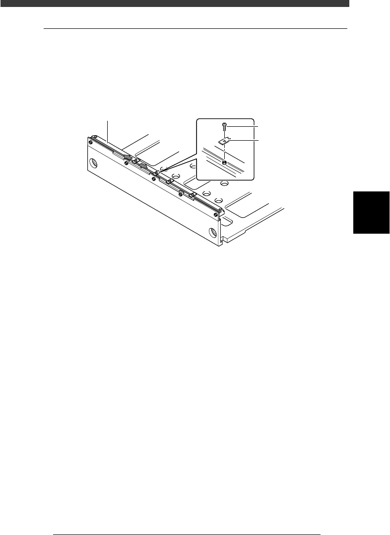
8.4 PCB support plates
The PCB support plates hold both edges of the PCB from above when the
PCB is secured in the mounting position. Each support plate is installed
with M3 screws on the conveyor rails. Adjust the positions of the PCB
support plates on the fixed (front) conveyor rail to match the PCB.
PCB support plates
23412-D8-00
Fixed conveyor rail
PCB support plat
e
M3 screw
e
1
Check that the machine is in emergency stop.
If not, press the emergency stop button.
2
Adjust the positions of PCB support plates.
Slightly loosen the screws (do not remove them) securing the PCB support
plates and adjust their positions by sliding them along the conveyor rail.
(Adjusting the PCB support plates on the movable (rear) conveyor rail is
unnecessary.)
1. Position the PCB support plate so its notch is aligned with the movable
locate pin.
2. Other support plates should be evenly distributed along the length of
the PCB.
3
Retighten the screws to secure the PCB support plates.
4
-32
4
Operation
Chapter 4
4
Daily operation
EPD8013110
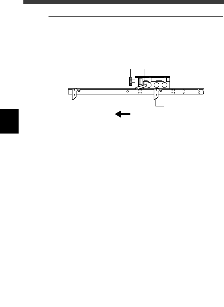
8.5 Transfer hook
The transfer hook located under the X-axis arm transfers the PCBs between
the carry-in conveyor, A/B tables and carry-out conveyor. When changing
the PCB type to be produced, adjust the transfer hook position so that it is
in the middle of the PCB width.
Transfer hook
23413-D8-00
Transfer hook
Transfer hook
Direction of PCB transfer
Transfer hook clamp leverTransfer hook slide dial
e
1
Check that the machine is in emergency stop.
If not, press the emergency stop button.
2
Loosen the clamp lever of the transfer hook slide dial.
Turn the clamp lever to the left to loosen it.
3
Adjust the transfer hook position.
Turn the transfer hook slide dial so the hook is positioned in the middle of
the PCB width.
4
Tighten the clamp lever of the transfer hook dial.
Turn the clamp lever to the right to lock it.
4
-33
Operation
Chapter 4
4
Daily operation
EPD8013110
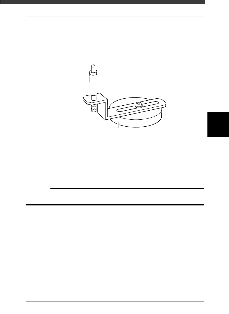
8.6 Push-up pins
The push-up pins are attached to the push-up plate by a magnet and used to
correct downward warping of the PCB. (When using these push-up pins,
set the PCB FixDevice parameter on the PCB Info. screen to “Pin+Push-
UP” or “Edge Clamp” (option).)
Push-up pin
23414-D8-00
Magnet stand
Pin shaft
e
1
Check that the machine is in emergency stop.
If not, press the emergency stop button.
2
Place the push-up pins in correct position on the push-up
plate.
Considering the shape and size of the PCB, place the push-up pins on the
push-up plate so that they uniformly support the PCB, including the edge
of the PCB.
c
CAUTION
Set the push-up pins in positions where they will not interfere with the conveyor rails
and other parts when the push-up plate is raised.
3
Set a PCB on the conveyor.
Raise the main stopper with the MAIN STOPPER command in the
CONVEYOR UNITS menu, then set a PCB on the conveyor and place it
against the main stopper.
4
Raise the push-up plate.
Use the PUSH UP command in the CONVEYOR UNIT menu to raise the
push-up plate.
5
Check that the PCB is uniformly clamped on the conveyor.
Lightly tap on the PCB and also check for warping of the PCB from the
side. If the PCB is supported evenly with no warping, the adjustment is
okay.
Reference
It may be convenient to mark the positions of the push-up pins on the plate (with a label,
magic marker, etc.) for each PCB type.