YV180X_Ope_E.pdf - 第303页
S -5 EPD8013110 Index Index Symbols [ACTIVE] key 1-13, 1-16 [Ctrl] + [F10] keys 5-143 [Ctrl] + [F9] keys 5-147 [F1] key 2-6 [F10] key 5-142, 5-146 [F2] key 5-8 [F3] key 5-12, 5-74, 5-91, 5-102 [F6] key 5-59, 5-82 [F9] ke…
S
-3
EPD8013110
Supplement
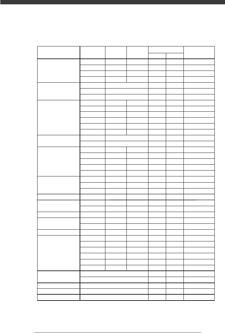
1. Nozzle table
Typical components and suitable nozzle types for multi-camera recognition
25001-D8-02
LWT
1.00
1.60
2.00
3.20
2.00
3.45
5.90
1.00
1.50
2.00
3.20
3.20~4.50
5.60
3.40
5.90
2.90
3.80
4.70
6.00
7.30
4.30
6.60
10.00
7.30
3.20
4.50
4.50
2.90
4.00
4.60
5.00
7.60
10.10
12.60
15.30
17.80
0.50
0.80
1.25
1.60
1.25
1.35
2.20
0.50
0.80
1.25
1.60
2.50~3.20
5.00
1.50
2.20
1.60
2.90
2.60
3.20
4.30
4.30
6.60
10.00
5.30
2.50
3.20
3.80
1.50
3.00
2.60
4.50
4.50
4.50
5.70
7.50
7.50
0.50
0.50
0.50
0.60
0.50
0.80
1.25
1.25
1.50~1.90
1.90
1.60
1.60
2.10
2.50
2.80
5.70
5.70
10.50
3.25
2.00
3.20
2.40
1.10
1.80
1.60
1.50
1.50
1.50
1.50
2.00
2.00
71F
72F
72F
72F
72F
72F
76F
71F
72F
72F
72F
73F
73F
72F
–
72F
73F
73F
73F
73F
73F
73F
–
73F
73F
73F
73F
72F
73F
73F
73F
73F
73F
73F
–
–
73F
–
–
–
–
71A
72A
72A
72A
72A
72A
76A
71A
72A
72A
72A
73A
73A
72A
76A
72A
73A
73A
73A
73A
73A
73A
74A
73A
73A
73A
73A
72A
73A
73A
73A
73A
73A
73A
74A
74A
73A
74A
74A
74A
74A
Type F Type A
Components
Box type chip
Cylindrical chip
(Melf type
component)
Ceramic capacitor
Tantalum electrolytic
capacitor
Aluminum electrolytic
capacitor
SOP (6 to 28P)
PLCC
QFP
BGA
Connector
Chip inductor
Semi-variable resistor
Mini-mold transistor
Power transistor
Chip film capacitor
Melf type capacitor
5✕5 to 10✕10
10✕10 to 25✕25
10✕10 to 25✕25
10✕10 to 25✕25
10✕10 to 25✕25
Nozzle Type
Required Nozzle
Setting in
Component Info.
For1005CHIP
For1608CHIP
For2125CHIP
For3216CHIP
ForMELF S
ForMELF M
ForMELF L
For1005CHIP
For1608CHIP
For2125CHIP
For3216CHIP
For4532CHIP
For5650CHIP
ForMELF M
ForMELF L
For3216CHIP
For4532CHIP
For5650CHIP
For7343CHIP
For7343CHIP
ForALC S
ForALC M
ForQFP 20mm
For7343CHIP
For4532CHIP
For4532CHIP
ForVR L
For3216CHIP
For4532CHIP
For5650CHIP
ForSOP 10mm
ForSOP 10mm
ForSOP 20mm
ForSOP 20mm
ForSOP 30mm
ForSOP 30mm
ForSOP 10mm
ForQFP 20mm
ForQFP 20mm
ForQFP 20mm
ForQFP 20mm*
*: When a special nozzle is used, set to "Sp.Nozzle A to F".

S
-5
EPD8013110
Index
Index
Symbols
[ACTIVE] key 1-13, 1-16
[Ctrl] + [F10] keys 5-143
[Ctrl] + [F9] keys 5-147
[F1] key 2-6
[F10] key 5-142, 5-146
[F2] key 5-8
[F3] key 5-12, 5-74, 5-91, 5-102
[F6] key 5-59, 5-82
[F9] key 5-141
[Fn] key 1-15
[SHIFT] + [F9] keys 5-109
[TAB] key 3-9
4-point fiducial function 6-28
A
Adjust Assistant
For badmark 6-44
For pattern matching 6-60
ADJUST ASSISTANT command
For component information 5-59
For mark information 5-82
Air blow timer 5-131
Alternative component function 6-51
Alternative component number 6-55
AUTO RUNNING command 4-16
Axis
Axis movement direction 3-6
Plus/minus directions 3-3
Selecting the axis 3-4
Selecting the axis speed 3-5
Axis configuration 3-3
AXIS GROUP key, YPU 1-13
B
Badmark
Block badmark 6-37
Local badmark 6-40
PCB badmark 6-37
Badmark function 6-36
Badmark information 6-43
BASIC INFO. parameters
BGA components 5-47
BGA components (simple BGA) 5-
43
Connectors 5-55
Melf components 5-24
Mini-mold transistor/SOT 5-28
QFP components 5-38
SOP components 5-33
Standard chip components 5-17
BGA components 5-42, 5-46
Adjusting the Binary Level 5-53
Editing the BGA ball lead information 5-50
Block badmark 6-37
Block conversion 6-9
Block repeat data 6-5
Block repeat data reconversion 6-12
Block repeat function 6-4
C
Caution 3
Chip resistors and capacitors 5-16
Component Info. screen 5-12
Component information
BGA components
BGA setting 5-46
Simple BGA setting 5-42
Connectors 5-54
Creating the component information 5-10
Melf components 5-23
Mini-mold transistor/SOT 5-27
QFP components 5-37
SOP components 5-32
Various parameter settings 5-15
Component recognition directions 5-15
CONDITION monitor 4-16
Connectors 5-54
CONVEY OUT PCB command 4-22
Conveyor unit 5-86
CONVEYOR UNIT command 3-7, 5-87
Conveyor unit operation 3-7
Conveyor unit setup flow 4-27
Conveyor width 4-29, 5-87
Copy
COPY SELECTED LINES command 5-149
Copying the specified range 5-148
SELECT DATA command 5-148
CYCLE STOP command 4-22
D
Data backup 5-136, 5-139
Data correction 5-117
Data editing 5-148
Data input and operation devices 1-12
Data optimization 5-111
CONDITION SETTING command 5-113
EXECUTE command 5-116

S
-6
EPD8013110
Index
Data replace 5-153
Component information 5-156
Mount information 5-153
REPLACE command 5-156
Data sort 5-159
DATA SORT command 5-159
DATA_FILE_MNG mode 5-137
DATA_GENERATOR mode 5-112
Database
Copying from the component
information 6-15
Copying from the mark information
6-15
Copying from the YAMAHA
database 6-17
User database 6-14
Delete
DELETE 1 LINE command 5-152
DELETE SELECTED LINES command
5-150
Deleting one line 5-152
Deleting the specified range 5-150
DISCARD COMP. command 5-64
DRAW THE SHAPE command 5-62
DUMP INFO. parameters
BGA components 5-48
BGA components (simple BGA) 5-
44
Connectors 5-56
Melf components 5-25
Mini-mold transistor/SOT 5-29
QFP components 5-39
SOP components 5-35
Standard chip components 5-20
E
Edge clamps 1-11
Emergency stop button 1-3
Error
Air blow error 5-131
Component feed error 5-128
Component height error 5-131
Component mount error 5-131
Component pickup error 5-128
Component recognition error 5-130
Correcting the data 5-133
Feeder error 5-129
Fiducial mark recognition error 5-
126
Mounting position error 5-133
Mounting position shift 5-134
Nozzle trouble 5-130, 5-132
PCB data error 5-125
PICK & MOUNT INFO. parameter error 5-
129, 5-132
Pickup height error 5-128
Reference pickup/mount vacuum levels 5-132
Error countermeasures 5-124
F
Feeder
Accessible feeders 1-10
Feeder operation 3-8
Feeder set position 1-9
FEEDER OUT MONITOR command 3-8
Feeder plate 1-9
Feeder set position
Optimizing the feeder set positions 6-54
Fiducial function
4-point fiducial function 6-32
Block fiducial function 6-25
Local fiducial function 6-27
PCB fiducial function 6-25
Point fiducial and local fiducial function 6-29
FIXED COMP.MATCH command. 6-22
Flying nozzle change 1-8
Function key 1-15
H
Head movement range 1-10
HELP key, YPU 1-13
I
Information monitor 4-17
INPUT/OUTPUT MONITOR command 3-9
Insert
INSERT 1 LINE command 5-151
Inserting one line 5-151
Inspection before operation 4-5
J
JOY STICK key, YPU 1-13
Joystick, YPU 1-13, 3-6
K
Key function 1-15
Keyboard 1-15