YV180X_Ope_E.pdf - 第107页
5 -31 EPD8008100 Operation Chapter 5 5 Creating the PCB data 66. ReflectLL Enter the projected length of leads which reflect light during recognition. Use the default setting in most cases. 67. LeadWidth Enter the correc…

5
-30
EPD8008100
Operation
Chapter 5
5
Creating the PCB data
For descriptions of the following VISION INFO. parameters, refer to
“3.3.1 Standard chip components” in this chapter.
44. Light Selection
45. Lighting Level
46. Comp. Threshold
47. Comp. Tolerance
48. Search Area
49. Datum Angle
50. Comp. Intensity
51. MultiCam. Marker
6. SHAPE INFO. parameters
Set these parameters after specifying the VISION INFO. parameters. If
“Alignment Type” is undefined, the following parameters are not dis-
played.
61. Body Size X, Body Size Y
Enter the correct dimensions including the leads, measured with a vernier
caliper or micrometer.
62. Body Size Z
Enter the correct thickness measured with a vernier caliper or micrometer.
63. Ruler Offset
Enter the distance in pixels from the end of the component to an imaginary
ruler line used to measure the lead width and pitch. Use the default setting
in most cases. (This parameter is displayed only when the Option Edit
parameter on the <3/1/A1 OPTION CONFIG.> screen is set to “Exist”.)
64. Ruler Width
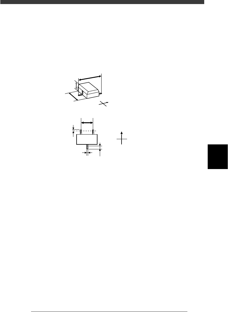
Enter the width of the leads provided on both ends of the component. (See
the drawing below.) This can be checked by executing the Adjust Assistant
explained later.
65. Lead Number
Enter the number of leads existing in the N and S directions.
NS directions
25506-C0-00
Pickup angle
Loading
position
0 deg. 90 deg.
NSNS
N
S
N
S
5
-31
EPD8008100
Operation
Chapter 5
5
Creating the PCB data
66. ReflectLL
Enter the projected length of leads which reflect light during recognition.
Use the default setting in most cases.
67. LeadWidth
Enter the correct lead width.
68. LeadPitch NS
Enter the correct lead pitch (lead-to-lead spacing).
SHAPE INFO. parameters and for mini-mold transistors
23511-C0-00
N
S
E
W
B
C
A
N
S
E
W
F
D
E
G
Bottom view
A : Body Size X
B : Body Size Y
C : Body Size Z
D : Ruler Offset
E : Reflect LL
F : Lead Pitch
G : Lead Width
5
-32
EPD8008100
Operation
Chapter 5
5
Creating the PCB data
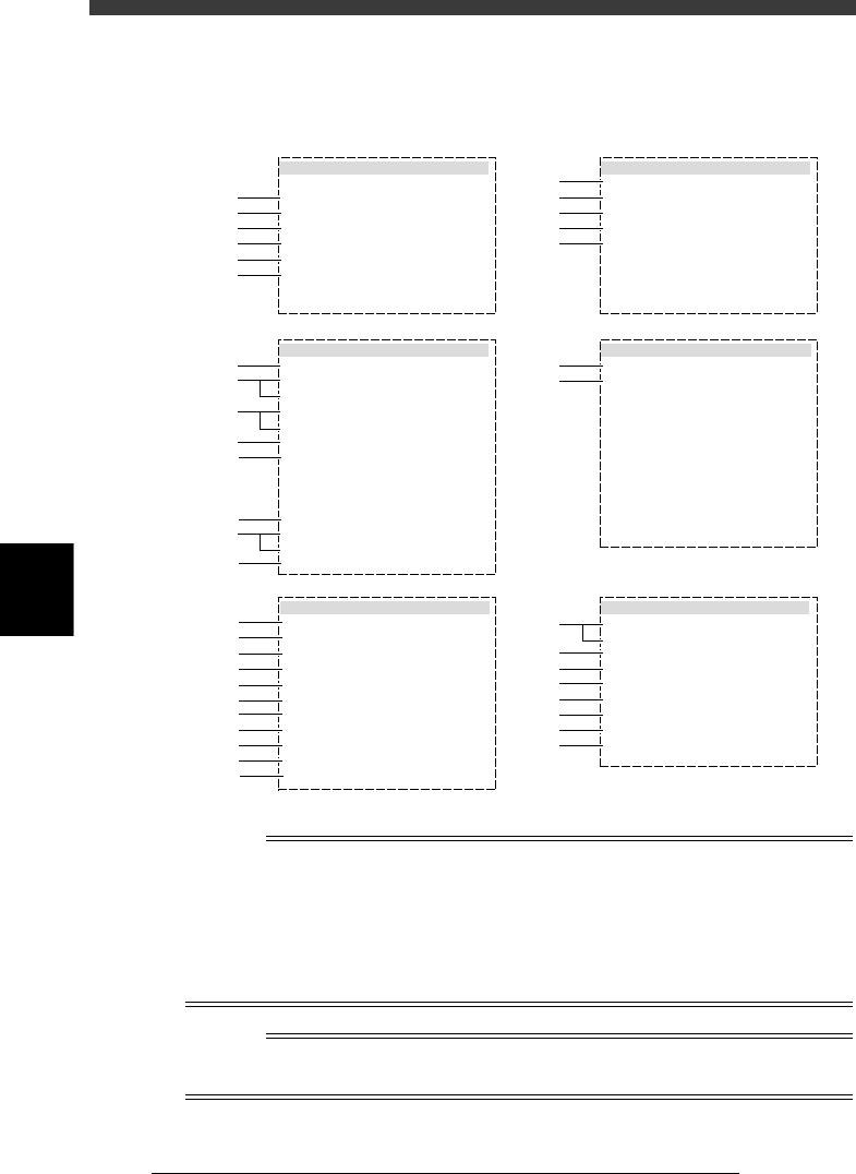
3.4.2 SOP components
SOP components are registered with the parameters shown below.
SOP component parameters
27513-D8-00
6. SHAPE INFO.
Body Size X mm
Body Size Y mm
Body Size Z mm
Ruler Offset
Ruler Width
Lead Number
ReflectLL mm
LeadWidth mm
LeadPitch mm
:
:
:
:
:
:
:
:
:
6.40
10.15
2.10
2
2
8
0.50
0.45
1.27
5. VISION INFO.
Alignment Group
Alignment Type
AlignmentModule
Light Selection
Lighting Level
Comp. Threshold
Comp. Tolerance
Search Area mm
Datum Angle
Comp. Intensit
MultiCam. Marker
:
:
:
:
:
:
:
:
:
:
:
IC
SOP
Fore&Back&Las
Main + Coax
6/8
Normal
NotUse
55
30
5.00
0
1 .BASIC INFO.
Database No.
Comp. Package
Feeder Type
Required Nozzle
Feeder Set No.
Pos. Definition
Feeder Pos_X mm
:
:
:
:
:
:
:
Tape
32mmSticky
ForSOP10mm73
Automatic
704
7
-9.80
2. OPTION INFO.
FixCmpRef.
AIt.Cmp
Use feeder opt.
Comp. Group No.
Correct Pickpos
:
:
:
:
:
Yes
Not Use
0
0
0
3. PICK AND MOUNT INFO.
Pick Angle deg
Pick Timer
Mount Timer
Pick Height
Mnt Height
Pick Sequence
Mount Action
Mount Speed
PickupSpeed
XY Speed
Vacuum Check
Pick Vacuum
Mount Vacuum
Conv. Y Speed
:
:
:
:
:
:
:
:
:
:
:
:
:
:
4. DUMP INFO.
Dump Way
Retry Times
:
:
Dump POS
2
s
s
mm
mm
%
%
%
%
%
0
0.15
0.05
Normal
NORMAL
100
100
100
NORMAL CHK
FAST
0.0
0.5
10
10
1
2
3
4
5
6
41
42
43
44
45
46
47
48
49
50
51
11
12
13
14
15
31
32
61
62
63
64
64
65
66
67
21
22
23
24
25
26
27
28
29
n
NOTE
When setting the parameters shown in the sub-windows above, use the number keys to set
the parameters aligned on the right, while using the [INS], [DEL] or [Space] key to set
the parameters aligned on the left. However, there are some parameters which should be
set or optimized with the Adjust Assistant commands described later in “3.7” in this
chapter.
The displayed parameters differ slightly depending on the <3/1/A1 OPTION CONFIG>
settings.
Reference
To make parameter settings in the TRAY INFO. sub-window when using a stick feeder, also
refer to “3.8 Setting the stick feeder component data” in this chapter.