YV180X_Ope_E.pdf - 第191页
5 -115 EPD8013110 Operation Chapter 5 5 Creating the PCB data 3 Quit the settings. Press the [ESC] key to close the DA T A GENERA T OR CONDITION box. This completes the settings for the DA T A GENERA T OR. Refer ence The…

5
-114
EPD8013110
Operation
Chapter 5
5
Creating the PCB data
• FEEDER SET CONDITION
0: NO
No mount data (mounting sequence, head selection and feeder set
position) is optimized.
1: ALL FEEDERS FIXED
The mounting sequence and head selection are optimized, but the
feeder set position is not optimized.
2: NO SET POS. FEEDERS MOVE
In addition to optimizing the mounting sequence and head selection,
the optimum feeder set number is assigned only to the component data
whose feeder position is unspecified (Feeder Set No. in the Component
Info. is set to “0”.)
3: MOVE WITHIN TABLE
In addition to optimizing the mounting sequence and head selection,
the optimum feeder set number is assigned all component data within
the front feeder plate when a feeder set number on the front feeder
plate was entered in the “Feeder Set No. column in the Component
Info, or within the rear plate when a feeder set number on the rear
feeder plate was entered in the “Feeder Set No. column in the Compo-
nent Info,
4: ALL FEEDERS MOVE*
In addition to optimizing the mounting sequence and head selection,
the optimum feeder set number is assigned to all component data
registered in the Component Info.
5: MOVE + FIXED COMP. MATCH
This setting allows performing the operations of “ALL FEEDERS MOVE”
and static component matching. (Refer to “4. Static components” in
Chapter 6 for detailed information.) This is invalid when static compo-
nents are not used.
• EDIT FEEDER PLATE
Here you can specify the feeder plate which should be selected
preferentially with data optimization.
EDIT FEEDER PLATE box
27545-C0-00
EDIT FEEDER PLATE
machine
Front plate
Use the [Space] [INS] or [DEL]
to make setting.
5
-115
EPD8013110
Operation
Chapter 5
5
Creating the PCB data
3 Quit the settings.
Press the [ESC] key to close the DATA GENERATOR CONDITION box.
This completes the settings for the DATA GENERATOR.
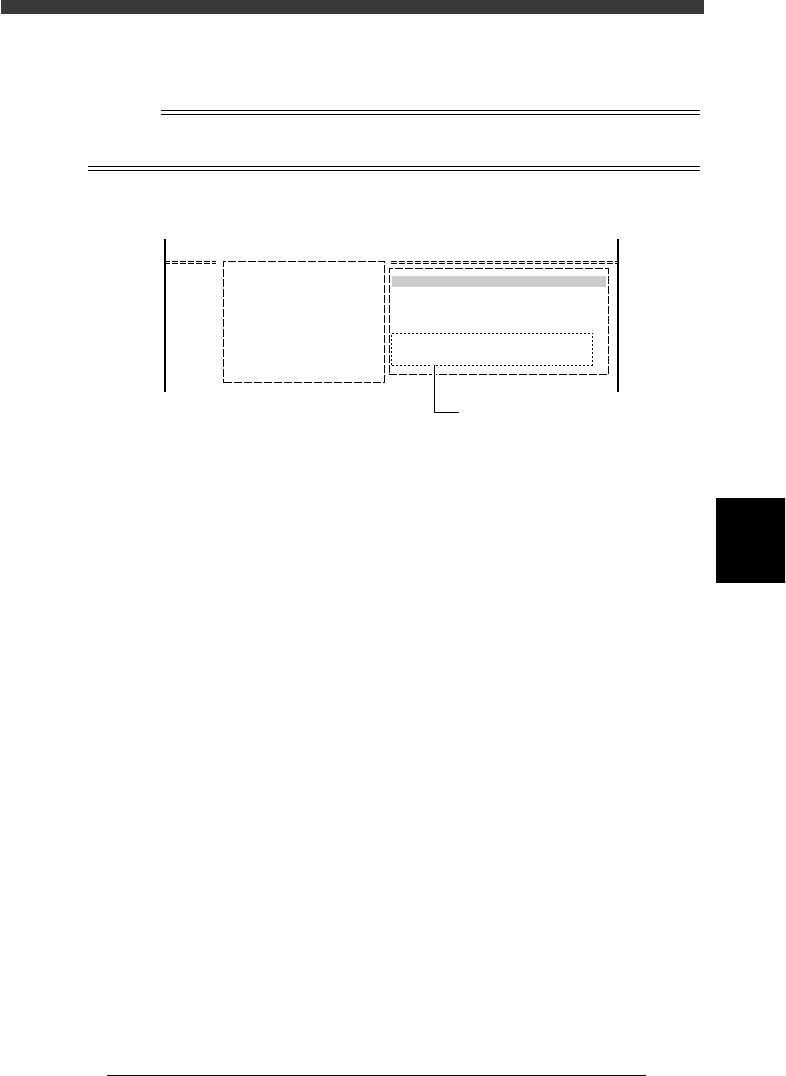
Reference
The setting conditions for data optimization are displayed in the DATA GENERATOR
OBJECT box as shown below.
DATA GENERATOR OBJECT box
27546-C0-00
A/SETTING & RUN
A4 CONDITION SETTING
DATA GENERATOR OBJECT
BLK. CONV. 0 : NO
FDR. POS. 4 : ALL FEEDERS MOVE
Data generator conditions

5
-116
EPD8013110
Operation
Chapter 5
5
Creating the PCB data
9.3 Optimizing the data
When you have selected the PCB and setting conditions, perform the data
optimization in the DATA GENERATOR mode.
1 Perform data optimization.
1. Select <2/2/A5 EXECUTE> and press the [ENTER] key.
The DATA GENERATOR SEQUENCE MONITOR box appears to start
the data optimization. When the optimization is complete, the
mounting data such as mounting cycle and number of mounting points
is displayed.
2. Press any key to return to the previous screen.
DATA GENERATOR monitor box and optimized results
27547-C0-00
DATA GENERATOR SEQUENCE MONITOR
PCB NAME PCB1 MACHINE
18. DISTRIBUTING MOUNT DATA
>>>>>>>>>>>>
2 Save the data.
Select <2/2/C5 RENAME & EXIT> and press the [ENTER] key. The opti-
mized data will be saved.
c
CAUTION
The original data will be overwritten when the optimized data is saved with the <2/2/C0
SAVE & EXIT> command. To keep the original data, rename and save the data with the
<2/2/C5 RENAME & EXIT> command.