YV180X_Ope_E.pdf - 第96页
5 -20 EPD8008100 Operation Chapter 5 5 Creating the PCB data components such as chip components, it is okay to set these parameters to “ 0.00 ” . 23. Pick Height, Mount Height These are the Z-axis height offset v alues u…
5
-19
EPD8008100
Operation
Chapter 5
5
Creating the PCB data
specifying an alternative component, see “8. Alternative components” in
Chapter 6.
13. Use feeder opt.
Set to “Yes” when you want to change the feeder set positions according to
results obtained with the DATA GENERATOR commands. (See “9. Data
optimization” in this chapter.) Set to “No” if you do not want to change
these positions. Setting to “Yes” is advised.
14. Comp. Group No.
When a nozzle lowers to mount a low-profile component after tall
components have been mounted on the PCB, the neighboring nozzles may
interfere with those tall components. To avoid this, components can be
grouped by height so that they are mounted in the desired order (0 to 99).
When no mounting order is needed, set this parameter to “0”.
15. Correct Pickpos.
Set this parameter to “NotUse” in normal operation.
3. PICK & MOUNT INFO. parameters
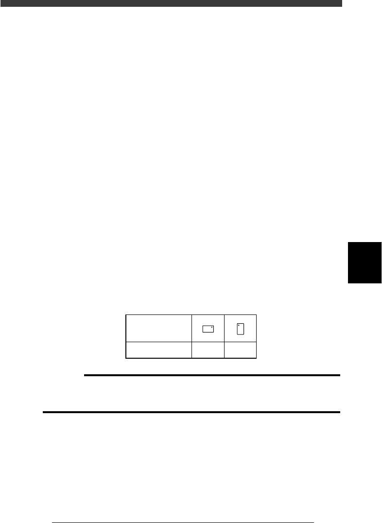
21. Pick Angle deg
This parameter specifies the angle through which the mounter head rotates
to pick up a component on the feeder. This setting determines the orienta-
tion of the component (recognition reference) when it is recognized and
displayed on the vision monitor. Normally, set this parameter to 0° for
horizontally long components in the loading position on the feeder, and set
to 90° for vertically long components. When you are using a bulk cassette
feeder, always set this parameter to 90°.
Chip component pickup angle
25503-C0-00
0 deg. 90 deg.
Loading position
Pickup angle
NS
E
W
N
S
WE
c
CAUTION
Pickup angle setting directly affects the recognition reference and mounting angle. Be
careful not to mistake 0° for 180° for horizontally long components in the loading
position and 90° for -90° for vertically long components.
22. Pick Timer, Mount Timer
These parameters specify the time duration (in seconds) for which the head
stays in the lowered position after detecting the reference pickup or mount
vacuum pressure when picking up or mounting a component. For small

5
-20
EPD8008100
Operation
Chapter 5
5
Creating the PCB data
components such as chip components, it is okay to set these parameters to
“0.00”.
23. Pick Height, Mount Height
These are the Z-axis height offset values used when the head lowers to
pick up or mount a component. Set these parameters to “0” in normal
operation.
If you want to lower the Z-axis height during component pickup or
mounting, enter a plus value in the Pick Height or Mount Height column.
Conversely, if you want to raise the Z-axis height, enter a minus value.
24. Pick Sequence
This parameter specifies the timing to start vacuum generation when the
head picks up a component. When set to “Normal”, vacuum generation
starts before the head moves down. When set to “Bottom”, vacuum
generation start after the head has moved down. Set this parameter to
“Normal” in most cases.
25. Mount Action
This specifies the nozzle descent movements during component mounting.
Set this parameter to “Normal” in most cases.
26. Vacuum Check
Set this parameter to “NORMAL CHK” in normal operation. If you want
to check pickup errors and mount errors strictly (head return without
mounting the component), set to “SPECIAL CHK”.
n
NOTE
When the Vacuum Check parameter is set to “NORMAL CHK”, the machine controls the
ascent timing of the head from the lowered position during component pickup or mount-
ing. This parameter setting is valid only when the Vacuum Check parameter on the PCB
Info. screen is set to “Check”.
27. Pick Vacuum, Mount Vacuum
These are reference vacuum pressures used for checking the pickup and
mount vacuum levels. Use the default settings and adjust them as needed
in the Adjust Assistant mode. (See “3.7” in this chapter.)
28. Conv. Y Speed
This parameter specifies the conveyor Y-axis moving speed. Set to “FAST”
as long as no problem occurs. But, if the mounted components move or
slide on the PCB due to the Y-axis movement, set this parameter to a
slower speed.
4. DUMP INFO. parameters
31. Dump Way
This specifies the location where a component will be dumped if an error

5
-21
EPD8008100
Operation
Chapter 5
5
Creating the PCB data
such as recognition error has occurred. Set to “Dump POS”. (See the
Discard point parameter explained in the mounter service manual.)
32. Retry Times
This determines how many times the machine will retry the same operation
if an error such as a recognition error has occurred. The number of retries
can be set from “NO RETRY” to “14”. When this retry setting is greater
than the machine data retry setting (Retry Limit parameter explained in the
mounter service manual), the machine data has priority.
5. VISION INFO. parameters
41. Alignment Group
Set this parameter to “Chip”.
42. Alignment Type
Set this parameter to “Std.Chip”.
43. AlignmentModule
This parameter specifies the lighting method for recognizing a component.
Use the default setting (Fore&Back&Laser) in most cases. Since the
YV180X surface mounters do not use “Back” (back light unit) and “Laser”
(laser unit), “Fore” (reflective lighting) is automatically selected.
44. Light Selection
Set this parameter to “Main + Coax” in most cases.
45. Lighting Level
This parameter specifies the reflected light brightness. Normally, use the
default setting and then optimize it in the Adjust Assistant mode (see
“3.7”).
46. Comp. Threshold
This parameter specifies the threshold level used to discern the light-
reflecting part (lead) from the background during component recognition.
Normally, use the default setting and then optimize it in the Adjust
Assistant mode (see “3.7”).
47. Comp. Tolerance
This specifies the tolerance for recognizing a component, in an allowable
error percentage of 0 to 100%. The larger the percentage, the greater the
tolerance. First use the default setting and then gradually increase it while
checking the recognition status monitored with the VISION TEST
command in the Adjust Assistant mode (see “3.7”).
48. Search Area
This parameter specifies the area within which the component leads are
searched. As this value is set larger, the search area is extended, but with a
loss in the image processing speed. First use the default setting and then
optimize it in the Adjust Assistant mode (see “3.7”).
49. Datum Angle
This parameter specifies the angle of component shape definition. Use the
default setting in most cases. (This parameter is displayed only when the
Option Edit parameter on the <3/1/A1 OPTION CONFIG.> screen is set to