YV180X_Ope_E.pdf - 第47页
4 -8 EPD8013110 Operation Chapter 4 4 Daily operation 4 3 T urn the servo ON. When the daily check item screen disappears and the VIOS main menu screen is displayed, release the emergency stop button and press the [READY…
4
-7
EPD8013110
Operation
Chapter 4
4
Daily operation
3.1 Turning the power ON
1
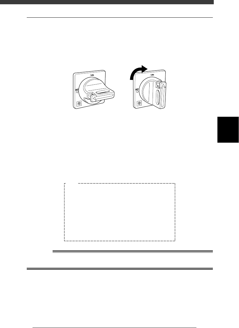
Turn the main power ON.
Turn on the main power switch at the front lower right of the machine, by
turning it to the right. The machine begins to load the program necessary
for machine operation.
Main power switch
21401-C0-00
ONOFF
2
Follow the instruction on the daily check items displayed
on the operation monitor.
The daily check items are displayed on the operation monitor after the
initial processing. Check each item as instructed and then press the
[ENTER] key. If maintenance is required, refer to Chapter 2 in the mounter
service manual.
Daily check items displayed on the operation monitor
27401-C0-00
E1045
<<Daily Examination>>
>NOZZLE TIP
>LEAF SPRING
>NOZZLE HOLDER
>LASER WINDOW
>CAMERA LENS
>FEEDER
>FEEDER PLATE
Please refer to the manuals in detail.
Ensure SAFETY and hit [ENTER] key.
<<Check>>
Break, Solder
Spring func.
Spring func.
Spring func.
Cleaning
Cleaning
Shutter
Cleaning
<<Predicted Error>>
Pick-up, Recognition
Pick-up, Comp. damage
Placement, Nozzle change
Pick-up, Comp. damage
Recognition
Recognition
Feeding, Pick-up
Placement, Pick-up
w
WARNING
BE SURE TO KEEP THE EMERGENCY STOP BUTTON PRESSED DURING
INSPECTION.

4
-8
EPD8013110
Operation
Chapter 4
4
Daily operation
4
3
Turn the servo ON.
When the daily check item screen disappears and the VIOS main menu
screen is displayed, release the emergency stop button and press the
[READY] button on the YPU or operation panel. The message “EMER-
GENCY STOP” disappears, and each axis is servo-controlled.
VIOS main menu display
27402-C0-00
<<<APPLICATION>>> 1/OPERATION/M 2/DATA/M 3/MAINTE/M 4/SHELL/M 0/EXIT
DATA[non ]
RUNNING
PRD.DATA
PRD.HISTORY
MANUAL
:Production, Warming up
:PCB data modification
:Production history
:Manual operation
<<<OPERATION MANAGER>>>
supports daily production.
MODE

4
-9
EPD8013110
Operation
Chapter 4
4
Daily operation
3.2 Return to origin
This operation returns each axis of the mounter and tray changer (if
connected) to the machine origin. After the power is turned on, return-to-
origin must be performed before beginning any work such as creation of
new PCB data and PCB production.
1. Return to origin in RUNNING mode
1
Select <1/1/RUNNING> and press the [ENTER] key.
A list of the registered PCB names appears on the screen.
2
Select the PCB name and press the [ENTER] key.
1. Use the arrow keys to select the name of the PCB to be produced.
If the PCB to be produced has not been registered yet, you can select
any PCB name.
2. Press the [ENTER] key to load the selected PCB data.
3. When the PCB data has been loaded, the cursor is positioned on <1/1/
D2 INIT. SERVO ORIGIN>.
3
Check the surrounding area for safety.
Each axis moves when you perform return-to-origin. Placing any part of
your body within the movement range of the head assembly during return-
to-origin can be hazardous, so be sure to stay out of the movement range.
4
Perform return-to-origin.
Check that the cursor is positioned on <1/1/D2 INIT. SERVO ORIGIN> and
press the [ENTER] key. Each axis begins to return to its origin.
2. Return to origin in MANUAL mode
1
Select <1(2 or 3)/4/MANUAL> and press the [ENTER] key.
When the alert message box “Incomplete return-to-origin” appears on the
screen, press the [ENTER] key to clear it.
Reference
The MANUAL mode is available in each manager except the SHELL manager.
2
Check the surrounding area for safety.
Each axis moves when you perform return-to-origin. Placing any part of
your body within the movement range of the head assembly during return-
to-origin can be hazardous, so be sure to stay out of the movement range.
3
Perform return-to-origin.
Move the cursor to <B6 INIT. SERVO ORIGIN> and press the [ENTER] key.
Each axis begins to return to its origin.