YV180X_Ope_E.pdf - 第183页
5 -107 EPD8013110 Operation Chapter 5 5 Creating the PCB data 8.2 Checking the mount information While displaying the component mounting position on the vision monitor , check and correct the mounting position, land patt…

5
-106
EPD8013110
Operation
Chapter 5
5
Creating the PCB data
8. Checking the data
It is suggested that you check the newly created data. This section explains
how to check the pickup position registered in the component information
and the mounting position registered in the mount information.
8.1 Checking the component information
When you have created component information while off-line and set the
Pos. Definition parameter to other than “Automatic”, you must check the
pickup position. Follow the steps below.
1 Open the Component Info. screen.
When the Component Info. screen is already displayed, skip this step.
When another edit screen is open, press the [F3] key (or select <2/1/A1>)
to display the edit item menu box, then select “Component Info.” and
press the [ENTER] key.
2 Set the component feeder on the feeder plate.
When you use a multistick feeder, securely install it on the feeder plate by
inserting the knock pins into the position that matches the Feeder Set No.
registered in the BASIC INFO. sub-window.
3 Check the pickup position.
You can use the trace function (see “12. Teaching and trace”) to check the
pickup position.
1. Move the cursor to the Feeder Pos_X parameter in the BASIC INFO.
sub-window.
2. Press the [F9] key (or run the <2/1/B0 TEACH, TRACE CONDITION>
command) and then set the following conditions.
Teaching table : A or B table
Teaching unit : Camera
Speed : About 20
Fiducial correction : NotUse
After setting the teaching (trace) conditions, the display returns to the
Component Info. screen.
3. Press the [F9] key to perform trace.
The camera moves to the pickup position that is currently registered.
Check that the correct pickup position is displayed on the vision
monitor.
4. If the pickup position is not correct, perform teaching referring to “3.10
Setting the stick feeder component data” to enter the correct pickup
position.
5
-107
EPD8013110
Operation
Chapter 5
5
Creating the PCB data
8.2 Checking the mount information
While displaying the component mounting position on the vision monitor,
check and correct the mounting position, land pattern names and compo-
nent numbers.
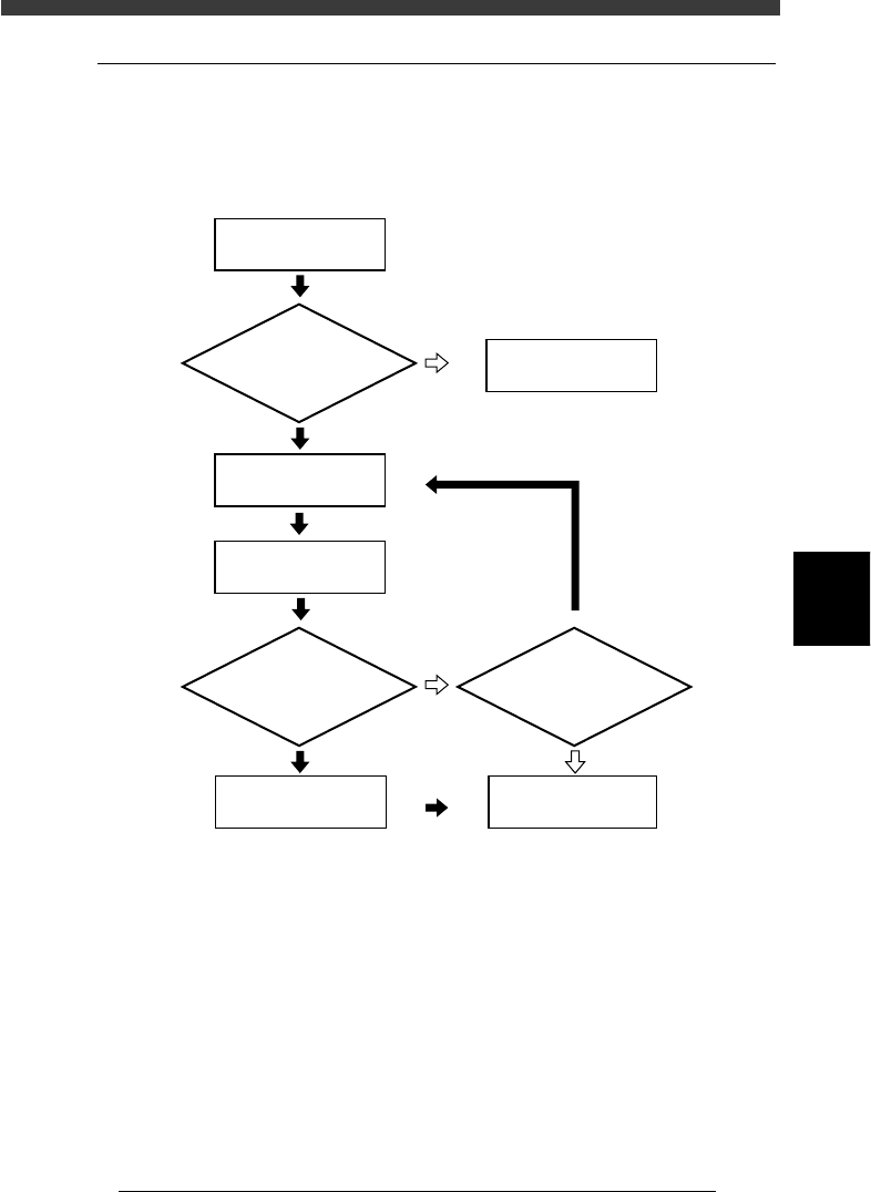
Flow chart for checking and correcting the mounting position
23549-C0-00
5
☞
Select mount number
whose mounting position
you want to check
Open Mount Info.
Check
mounting position
Teach optimum
coordinate data
Save data
Is PCB clamped?
Correct component
mounting position ?
Continue?
Clamp the PCB
YES
YES
YES
NO
NO
NO
5
-108
EPD8013110
Operation
Chapter 5
5
Creating the PCB data
1 Open the Mount Info. screen.
When the Mount Info. screen is already displayed, skip this step.
When another edit screen is open, press the [F3] key (or select <2/1/A1>)
to display the edit item menu box, then select “Mount Info.” and press the
[ENTER] key.
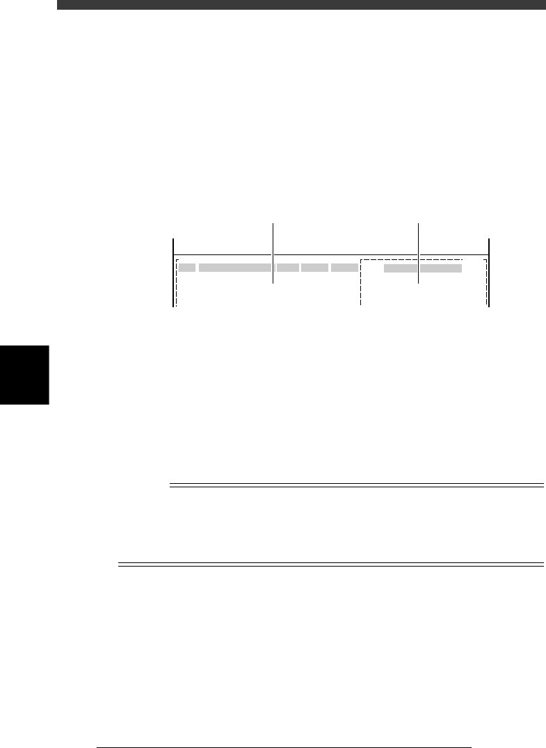
2 Press the [F4] key to co-display the Component Info.
screen.
Pressing the [F4] key displays part of the Component Info. on the right of
the screen. Use the [TAB] key to move the cursor between the Mount Info.
on the left and the Component Info. on the right of the screen.
Mount Info. and Component Info. screen
27540-C0-00
No.
1
2
3
COMPONENT NAME
R1608
R2125
R3126
OBJ:
F 20
F 21
F 22
PCB :
SignOfLandPattern Comp
X
Y
OBJ :Mount Info
No.
1
2
3
<<<APPLICATION>>> 2/DATA/M
<<MODE>>1/EDIT_DATA
Mount Info. Component Info.
3 Set the conditions to check the position.
Press the [F10] key (or run the <2/1/B0 TEACH, TRACE CONDITION>
command) and then set the following conditions.
Teaching table : A or B table
Teaching unit : Camera
Speed : 20 to 40
Fiducial correction : For PCB data using fiducial mark, select
“Use”.
For PCB data using no fiducial mark, select “NotUse”.
After setting the teaching conditions, the display returns to the Mount Info.
screen.
n
NOTE
When you correct, add or create the PCB data using fiducial marks, setting “FIDUCIAL
SEL” (fiducial correction) to “Use” allows the machine to recognize fiducial marks on the
PCB so that corrected mount data is automatically obtained. This makes it possible to
perform accurate teaching or tracing of the specified position. To use this function, the
fiducial mark coordinates and mark data must be set correctly in advance.