YV180X_Ope_E.pdf - 第181页
5 -105 EPD8013110 Operation Chapter 5 5 Creating the PCB data 9 Set the “ Skip? ” column. Select “ Exec. ” to use this mount data, and select “ Skip ” when not using it. n NOTE If block con version in <2/2/DA T A_GENE…
5
-104
EPD8013110
Operation
Chapter 5
5
Creating the PCB data
Reference
To perform teaching at a mounting position, set the teaching conditions as follows.
TEACH-TABLE SEL. (Teaching table): Select the A or B table head you will use.
TEACH-UNIT SEL. (Teaching unit) : Camera
SPEED SELECT (Axis moving speed) : 10 to 20
FIDUCIAL SEL (Fiducial correction) : Use (Select “NotUse” if not using
a fiducial mark.)
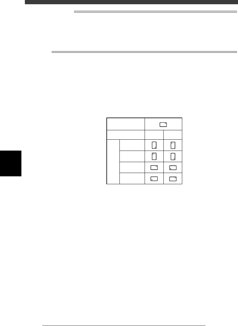
5 Enter the mounting angle in the “R” column.
Enter the angle through which the component must be rotated after
recognition before it is mounted on the PCB. When the pickup angle (in
the PICK AND MOUNT INFO. sub-window of the Component Info.) is 0°,
enter the rotating angle from the loading position, with the counterclock-
wise direction specified as a plus value when viewed from above. When
the pickup angle is 90° or -90°, see the table below.
Mounting angle
25517-C0-00
Loading position
Pickup angle
90 deg. -90 deg.
0 deg.
180 deg.
90 deg.
-90 deg.
Mounting angle
6 Check the head number in the “Head” column.
The head number to be used for mounting is indicated in the “Head”
column. Since the optimum head number is automatically selected when
you run the DATA_GENERATOR command described later, it is not
necessary to enter it here. (Refer to “9. Data optimization” in this chapter
for details.)
If you do not use the DATA_GENERATOR command, enter the head
number you will use for component mounting.
7 Set the fiducial mark number in the “FidMk” column.
Enter the number of the fiducial mark (point, local or 4-point fiducial) to
be used for this mount data. (Refer to “5.2 Local fiducial function” in
Chapter 6.) Note that this setting is valid only when necessary data is input
in the Local Fidu. Info. Enter “0” when not using the fiducial function.
8 Set the badmark number in the “BadMk” column.
Enter the number of the local badmark to be used for this mount data.
(Refer to “6.2 Local badmark” in Chapter 6.) Note that this setting is valid
only when necessary data is input in the LocalBadMrkInfo. Enter “0” when
not using the local badmark function.

5
-105
EPD8013110
Operation
Chapter 5
5
Creating the PCB data
9 Set the “Skip?” column.
Select “Exec.” to use this mount data, and select “Skip” when not using it.
n
NOTE
If block conversion in <2/2/DATA_GENERATOR> runs on the multi-block PCB data (to
convert multi-block PCB data into single PCB data), the “Exec” settings in the original
data will be saved as “NOTE DATA”.
0 Save the data.
After setting all mount data, press the [ESC] key twice to exit the current
edit screen, then select <2/1/D8 SAVE PCB DATA> and press the [ENTER]
key.

5
-106
EPD8013110
Operation
Chapter 5
5
Creating the PCB data
8. Checking the data
It is suggested that you check the newly created data. This section explains
how to check the pickup position registered in the component information
and the mounting position registered in the mount information.
8.1 Checking the component information
When you have created component information while off-line and set the
Pos. Definition parameter to other than “Automatic”, you must check the
pickup position. Follow the steps below.
1 Open the Component Info. screen.
When the Component Info. screen is already displayed, skip this step.
When another edit screen is open, press the [F3] key (or select <2/1/A1>)
to display the edit item menu box, then select “Component Info.” and
press the [ENTER] key.
2 Set the component feeder on the feeder plate.
When you use a multistick feeder, securely install it on the feeder plate by
inserting the knock pins into the position that matches the Feeder Set No.
registered in the BASIC INFO. sub-window.
3 Check the pickup position.
You can use the trace function (see “12. Teaching and trace”) to check the
pickup position.
1. Move the cursor to the Feeder Pos_X parameter in the BASIC INFO.
sub-window.
2. Press the [F9] key (or run the <2/1/B0 TEACH, TRACE CONDITION>
command) and then set the following conditions.
Teaching table : A or B table
Teaching unit : Camera
Speed : About 20
Fiducial correction : NotUse
After setting the teaching (trace) conditions, the display returns to the
Component Info. screen.
3. Press the [F9] key to perform trace.
The camera moves to the pickup position that is currently registered.
Check that the correct pickup position is displayed on the vision
monitor.
4. If the pickup position is not correct, perform teaching referring to “3.10
Setting the stick feeder component data” to enter the correct pickup
position.