YV180X_Ope_E.pdf - 第98页
5 -22 EPD8008100 Operation Chapter 5 5 Creating the PCB data “ Exist ” .) 50. Comp. Intensity This parameter specifies the threshold level used to measure the intensity in the outline area of a component after it is suce…

5
-21
EPD8008100
Operation
Chapter 5
5
Creating the PCB data
such as recognition error has occurred. Set to “Dump POS”. (See the
Discard point parameter explained in the mounter service manual.)
32. Retry Times
This determines how many times the machine will retry the same operation
if an error such as a recognition error has occurred. The number of retries
can be set from “NO RETRY” to “14”. When this retry setting is greater
than the machine data retry setting (Retry Limit parameter explained in the
mounter service manual), the machine data has priority.
5. VISION INFO. parameters
41. Alignment Group
Set this parameter to “Chip”.
42. Alignment Type
Set this parameter to “Std.Chip”.
43. AlignmentModule
This parameter specifies the lighting method for recognizing a component.
Use the default setting (Fore&Back&Laser) in most cases. Since the
YV180X surface mounters do not use “Back” (back light unit) and “Laser”
(laser unit), “Fore” (reflective lighting) is automatically selected.
44. Light Selection
Set this parameter to “Main + Coax” in most cases.
45. Lighting Level
This parameter specifies the reflected light brightness. Normally, use the
default setting and then optimize it in the Adjust Assistant mode (see
“3.7”).
46. Comp. Threshold
This parameter specifies the threshold level used to discern the light-
reflecting part (lead) from the background during component recognition.
Normally, use the default setting and then optimize it in the Adjust
Assistant mode (see “3.7”).
47. Comp. Tolerance
This specifies the tolerance for recognizing a component, in an allowable
error percentage of 0 to 100%. The larger the percentage, the greater the
tolerance. First use the default setting and then gradually increase it while
checking the recognition status monitored with the VISION TEST
command in the Adjust Assistant mode (see “3.7”).
48. Search Area
This parameter specifies the area within which the component leads are
searched. As this value is set larger, the search area is extended, but with a
loss in the image processing speed. First use the default setting and then
optimize it in the Adjust Assistant mode (see “3.7”).
49. Datum Angle
This parameter specifies the angle of component shape definition. Use the
default setting in most cases. (This parameter is displayed only when the
Option Edit parameter on the <3/1/A1 OPTION CONFIG.> screen is set to
5
-22
EPD8008100
Operation
Chapter 5
5
Creating the PCB data
“Exist”.)
50. Comp. Intensity
This parameter specifies the threshold level used to measure the intensity
in the outline area of a component after it is sucessfully identified by
normal vision recognition. If the measured intensity level is lower than this
threshold, the recognition result is viewed as an error. (This parameter is
enabled only when “Alignment Type” is set to “Std.Chip”.
51. MultiCam. Marker
When this parameter is set to “Use”, the multi-vision camera recognizes
the reference marker(s) provided on the head assembly and the results are
reflected on component recognition. This function is effective in maintain-
ing recognition accuracy even if the machine precision degrades with
operating time, but the recongnition time becomes longer.
6. SHAPE INFO. parameters
Set these parameters after specifying the VISION INFO. parameters. If
“Alignment Type” is undefined, the following parameters are not dis-
played.
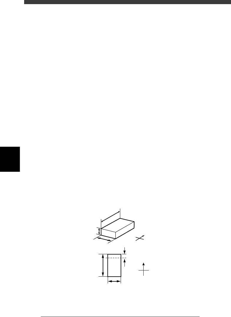
61. Body Size X, Body Size Y
Enter the correct dimensions measured with a vernier caliper or microme-
ter.
62. Body Size Z
Enter the correct thickness measured with a vernier caliper or micrometer.
63. Ruler Offset
This parameter specifies the distance in pixels, from the end of the
component to an imaginary ruler line used to measure the lead width. Use
the default setting in most cases.
SHAPE INFO. parameters for chip components
23508-C0-00
N
S
E
W
A
A
C
B
D
B
N
S
E
W
A : Body Size X
B : Body Size Y
C : Body Size Z
D : Ruler Offset
5
-23
EPD8008100
Operation
Chapter 5
5
Creating the PCB data
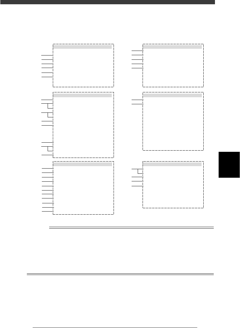
3.3.2 Melf components (cylindrical components)
Melf components are registered with the parameters shown below.
MELF component parameters
27511-D8-00
6. SHAPE INFO.
Body Size X
Body Size Y
Body Size Z
Ruler Offset
LeadWidth
:
:
:
:
:
1.25
2.00
1.25
3
0.40
5. VISION INFO.
Alignment Group
Alignment Type
AlignmentModule
Light Selection
Lighting Level
Comp. Threshold
Comp. Tolerance
Search Area mm
Datum Angle
Comp. Intensity
MultiCam. Marker
:
:
:
:
:
:
:
:
:
:
:
Chip
Melf Chip
Fore&Back&Las
Main + Coax
6/8
Normal
NotUse
55
30
1.50
0
1. BASIC INFO.
Database No.
Comp. Package
Feeder Type
Required Nozzle
Feeder Set No.
Pos. Definition
Feeder Pos_X mm
:
:
:
:
:
:
:
Tape
8mm Tape
ForMELF S 72
Automatic
521
10
39.79
2. OPTION INFO.
FixCmpRef.
AIt.Cmp
Use feeder opt.
Comp. Group No.
Correct Pickpos
:
:
:
:
:
Yes
Not Use
0
0
0
3. PICK AND MOUNT INFO.
Pick Angle deg
Pick Timer
Mount Timer
Pick Height
Mnt Height
Pick Sequence
Mount Action
Mount Speed
PickupSpeed
XY Speed
Vacuum Check
Pick Vacuum
Mount Vacuum
Conv. Y Speed
:
:
:
:
:
:
:
:
:
:
:
:
:
:
4. DUMP INFO.
Dump Way
Retry Times
:
:
Dump POS
2
s
s
mm
mm
%
%
%
%
%
0
0.00
0.00
Normal
NORMAL
100
100
100
NORMAL CHK
FAST
0.5
0.5
50
50
1
2
3
4
5
6
41
42
43
44
45
46
47
48
49
50
51
11
12
13
14
15
31
32
61
62
63
64
21
22
23
24
25
26
27
28
29
n
NOTE
When setting the parameters shown in the sub-windows above, use the number keys to set
the parameters aligned on the right, while using the [INS], [DEL] or [Space] key to set
the parameters aligned on the left. However, there are some parameters which should be
set or optimized with the Adjust Assistant commands described later in “3.7” in this
chapter.
The displayed parameters differ slightly depending on the <3/1/A1 OPTION CONFIG>
settings.