YV180X_Ope_E.pdf - 第20页
1 -10 EPD8013110 Operation Chapter 1 1 Par t names and functions 3.1 Head movement range (accessible feeders) Some feeders cannot be reached by a head depending on the head assembly configuration and X-axis mo vement ran…
1
-9
EPD8013110
Operation
Chapter 1
1
Part names and functions
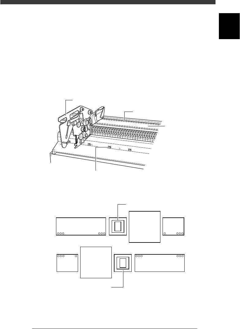
3. Feeder plate
Tape feeders, bulk feeders and stick feeders (multi-stick feeders) are
installed on the front and rear feeder plates of the machine. These feeders
pneumatically operate by air supplied from the mounter to feed each
component to the pickup position.
The YV180X feeder plate is separated into 4 plates. Two each are installed
on the A-table and B-table sides. Each feeder set position is designated by
a “feeder set number” as shown below.
Feeder plate
23104-D8-00
Feeder drive air outlet
Power supply connector for multi-stick
feeder and dump station
Tape feeder
Feeder plat
e
Feeder set number on standard machine (top view)
23105-D8-00
140
109 108 101
18
9
40
Multi-vision camera
Multi-vision camera
B table
A table
1
-10
EPD8013110
Operation
Chapter 1
1
Part names and functions
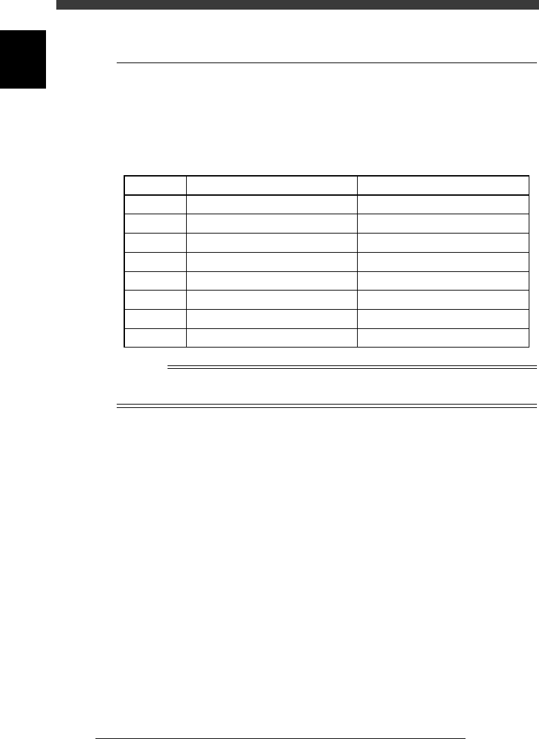
3.1 Head movement range (accessible
feeders)
Some feeders cannot be reached by a head depending on the head assembly
configuration and X-axis movement range. The table below shows feeder
numbers that can be accessed by each head when 8mm tape feeders are
installed on the feeder plate.
Accessible feeders (standard machine)
25102-D8-00
Head No.
1
2
3
4
5
6
7
8
Accessible feeder No. (front)
7 to 40
6 to 39
5 to 38
4 to 37
3 to 36
2 to 35
1 to 34
1 to 33
Accessible feeder No. (rear)
107 to 140
106 to 139
105 to 138
104 to 137
103 to 136
102 to 135
101 to 134
101 to 133
Reference
The number of accessible feeders depends on the machine specifications. If your machine
is custom-manufactured, see the spec sheet for your machine.
1
-11
EPD8013110
Operation
Chapter 1
1
Part names and functions
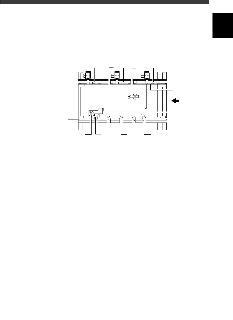
4. Conveyor unit
The YV180X has two conveyor tables (A tables and B tables). Each
conveyor table uses the following units to clamp a PCB in the mounting
position.
Conveyor unit (top view)
23106-D8-00
PCB
Movable
conveyor rail
Fixed
conveyor rail
12
2
3
7
4
7
5
7
6
6
1. Main stopper
When a PCB is carried in on the conveyor, the main stopper halts
travel of the PCB in the component mounting position.
2. Locate pins
These pins engage with the positioning holes of the PCB to secure it in
place ready for mounting. The locate pin on the downstream side is
fixed, but the locate pin on the upstream side is movable. The movable
locate pin must be adjusted according to the size of the PCB.
3. PCB support plate
These plates hold both edges of the PCB from above when the PCB is
secured in the mounting position.
4. Push-up plate
The push-up plate clamps the PCB up against the conveyor rails, with
the supporter pins attached by magnet on the plate.
5. Push-up pins
These pins are arranged on the push-up plate and secure the PCB by
pushing it up from the bottom.
6. PCB clamp
The PCB clamp secures the PCB by pushing its edges up against the
PCB support plates.
7. Edge clamps (option)
The edge clamps secure the PCB in the mounting position by pushing
laterally on the PCB edge.