YV180X_Ope_E.pdf - 第289页
6 -54 EPD8013110 Operation Chapter 6 6 Using various functions 6 8.2 Optimizing the feeder set positions The feeder set position is not yet specified for the multiplied component data, so you should execute the Da ta Gen…

6
-53
EPD8013110
Operation
Chapter 6
6
Using various functions
7 Check the data.
You should check that the number of feeders including the multiplied
result does not exceed the number of feeders that can be installed on the
machine. To check, press the [ESC] key to display the COMP. INF.
COMMAND menu box, then select “DATA CHECK” and press the [ENTER]
key. When no alarm message appears, the data settings are okay.
8 Save the data and quit the command.
Press the [ESC] key to display the COMP. INF. COMMAND menu box
again, then select “SAVE & QUIT” and press the [ENTER] key.
If you do not want to save the multiplied component data, select “EXIT
WITHOUT SAVING” and press the [ENTER] key.

6
-54
EPD8013110
Operation
Chapter 6
6
Using various functions
6
8.2 Optimizing the feeder set positions
The feeder set position is not yet specified for the multiplied component
data, so you should execute the Data Generator command to designate the
optimum feeder set positions.
1 Select <2/2/A4 CONDITION SETTING> and press the
[ENTER] key.
The DATA GENERATOR CONDITION box then appears. Set the conditions
as explained below. After making settings, press the [ESC] key to close the
DATA GENERATOR CONDITION box.
• BLOCK CONVERSION CONDITION
Set to “No”. (See “9. Data Optimization” in Chapter 5 for more details.)
• FEEDER SET CONDITION
Set to “4: ALL FEEDERS MOVE”. This setting allows optimizing the
feeder set positions for all component data.
2 Execute the Data Generator command.
Press the [ESC] key to exit the current menu box, then select <2/2/A5
EXECUTE> and press the [ENTER] key.
3 Save the data.
After the optimization is completed, select <2/2/B0 SAVE & EXIT” and
press the [ENTER] key. The optimized data will be saved.
Reference
When optimizing the feeder position only for newly multiplied data (with feeder set
numbers for other data left unchanged), enter “0” in the Feeder Set No. column of
the“Component Info.”. Then, return to the DATA GENERATION CONDITION box
by executing <2/2/A4 CONDITION SETTING>, and set the FEEDER SET
CONDITION parameter to “2: NO SET POS. FEEDERS MOVE”.
6
-55
EPD8013110
Operation
Chapter 6
6
Using various functions
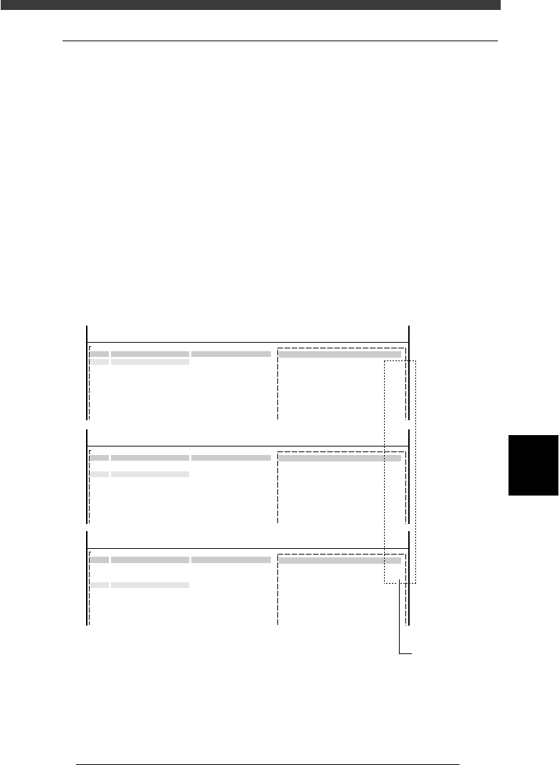
8.3 Alternative component number
After multiplying the component data, check that the correct number is
input for the “Alt.Cmp” parameter in the component information.
1 Open the Component Info. screen.
Open the Component Info. screen of the PCB data for which you per-
formed component data multiplication in the <2/1/EDIT_DATA> mode.
2 Check the alternative component number.
Line up the cursor with the component data designated as the alternative
component, and check that the correct number is entered in “Alt.Cmp.” on
the BASIC INFO. sub-window.
For example, when No. 1, 2 and 3 in the component information are
specified as an alternative component group, check that “2” is entered in
“Alt.Cmp.” for No.1, “3” for No. 2, and “1” for No. 3. This means that the
alternative component for No. 1 is No. 2, that for No. 2 is No. 3, and that
for No. 3 is No. 1, just like making a loop of 1→2→3→1 in the alternative
component group.
Checking the alternative component number
27635-C0-00
<<<APPLICATION>>> 2/DATA/M
<<MODE>> 1/EDIT_DATA
PCB :
OBJ :Component Info.
No.
1
2
3
4
5
6
7
COMPONENT NAME
R1608
R1608
R1608
COMMENT
2.OPTION INFO.
Alt. Cmp
:
2
<<<APPLICATION>>> 2/DATA/M
<<MODE>> 1/EDIT_DATA
PCB :
OBJ :Component Info.
No.
1
2
3
4
5
6
7
COMPONENT NAME
R1608
R1608
R1608
COMMENT
2.OPTION INFO.
Alt. Cmp
:
3
<<<APPLICATION>>> 2/DATA/M
<<MODE>> 1/EDIT_DATA
PCB :
OBJ :Component Info.
No.
1
2
3
4
5
6
7
COMPONENT NAME
R1608
R1608
R1608
COMMENT
2.OPTION INFO.
Alt. Cmp
:
1
Check her
e