YV180X_Ope_E.pdf - 第163页
5 -87 EPD8013110 Operation Chapter 5 5 Creating the PCB data 1 Run the <2/1/B7 CONVEYOR UNIT> command. The conveyor unit menu box appears as shown below . The sensor detection status is displayed to the right of ea…
5
-86
EPD8013110
Operation
Chapter 5
5
Creating the PCB data
5. Clamping the PCB
When you clamp a PCB on the conveyor manually, for example when
teaching the coordinate data on the PCB, set it on the conveyor with the
procedure below.
There are three methods of clamping a PCB. Select the method that
matches the PCB to be used.
1. “Locate Pin”
2. “Pin+PushUp”
3. “Edge Clamp” (option)
Methods 1 and 2 use the locate pins for PCB positioning but method 3 does-
not use locate pins. Refer to “8. Changing the conveyor unit setup” in
Chapter 4 for adjustment of each conveyor unit.
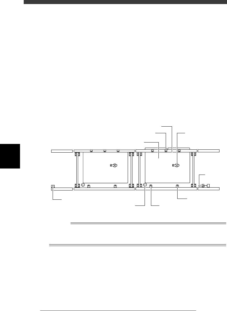
Conveyor unit (top view)
23536-D8-00
Edge clamp (option)
PCB clamp
Push-up plate
Push-up pin
Main stopper
A-table conveyor
B-table conveyor
Fixed locate pin
Movable locate pin
Entrance
stopper
Exit stopper
Reference
The PCB clamping method can be selected by specifying the PcbFixDevice parameter on
the PCB Info. screen. For details on the PCB clamping method, refer to Step 12 of “6.
Creating the PCB information” in this chapter.
5
-87
EPD8013110
Operation
Chapter 5
5
Creating the PCB data
1 Run the <2/1/B7 CONVEYOR UNIT> command.
The conveyor unit menu box appears as shown below. The sensor
detection status is displayed to the right of each unit.
Conveyor unit menu box
27535-C0-00
LOCATE PIN
PUSH UP
PCB CLAMP
EDGE CLAMP
PUSH IN
MAIN STOPPER
ENT. STOPPER
EXIT STOPPER
CONV. MOTOR
CONV. WIDTH
PROGRAM PIN
RETURN
CONVEYOR UNIT (STS.)
OFF
OFF
OFF
OFF
OFF
OFF
OFF
OFF
OFF
OFF
2 Check the surrounding area for safety.
Check that the push-up pins are not placed on the push-up plate so that
they do not interfere with the conveyor rails when the conveyor width is
adjusted.
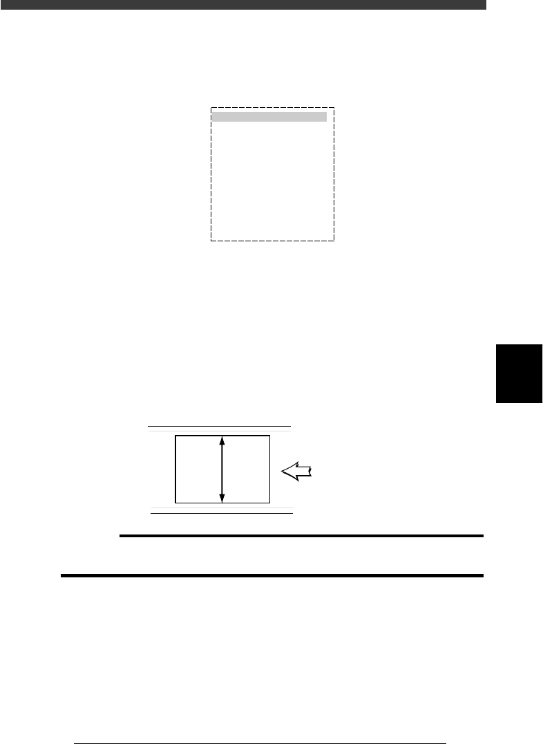
3 Adjust the conveyor width.
Select “CONVEYOR WIDTH” from the CONVEYOR UNIT menu box and
press the [ENTER] key. The PCB width input box then appears. Input the
PCB width value in millimeters and press the [ENTER] key, the conveyor
width will then be adjusted.
PCB width
23537-C0-00
PCB
width
PCB flow direction
c
CAUTION
The conveyor width moves when you press the [ENTER] key after inputting the PCB
width, so use caution.
e
4 Set emergency stop.
Press the emergency stop button for safety.
5 Raise the main stopper.
Move the cursor to “MAIN STOPPER” and press the [ENTER] key. (The
main stopper rises and lowers each time you press the [ENTER] key. )
6 Set the PCB on the conveyor.
Place the PCB against the main stopper to set it on the conveyor.

5
-88
EPD8013110
Operation
Chapter 5
5
Creating the PCB data
7 Check and adjust the locate pin positions.
Check and adjust the locate pin positions so that they are aligned with the
center of the PCB positioning hole.
(This step is unnecessary when the PCB clamping method is “Edge
Clamp”.)
8 Set the push-up pins.
Set the push-up pins in proper positions on the push-up plate so that they
support the PCB from the back side when the push-up plate is raised.
(This step is unnecessary when the PCB clamping method is “Locate Pin”.)
9 Raise the locate pins.
Move the cursor to “LOCATE PIN” and press the [ENTER] key. The locate
pins rise and lower each time you press the [ENTER] key. Check that the
locate pins are securely inserted into the PCB positioning holes.
(This step is unnecessary when the PCB clamping method is “Edge
Clamp”.)
0 Cancel emergency stop and raise the push-up plate.
Move the cursor to “PUSH UP” and press the [ENTER] key. The push-up
plate rises and lowers each time you press the [ENTER] key.
(This step is unnecessary when the PCB clamping method is “Locate Pin”.)
q Quit the CONVEYOR UNITS command.
Press the [ESC] key (or select “RETURN”) to quit the CONVEYOR UNITS
command and return to the previous screen.