YV180X_Ope_E.pdf - 第276页
6 -41 EPD8013110 Operation Chapter 6 6 Using various functions Local badmark XY coordinates 23615-C0-00 X X Y Y <Relative to PCB origin> <Relative to block repeat No.1> Badmark Badmark PCB origin Block repeat…

6
-40
EPD8013110
Operation
Chapter 6
6
Using various functions
6
6.2 Local badmark
The local badmark function cancels component mounting by recognizing a
badmark specified at a mounting point.
n
NOTE
The local badmark function allows the machine to automatically switch the type of
production PCB. For more details, refer to “7. Self production control” in this chapter.
To use the badmark function, enter the following settings.
c
CAUTION
The following procedure for setting the local badmark function is explained, assuming
that you already have the complete PCB data needed for component mount. If you are
not yet finished with creating the PCB data, complete the PCB data after first referring
to Chapter 5 in this manual and then set the fiducial function.
1 Create the mark information.
On the Mark Info. screen you must first create the mark information on the
local badmarks to be used. (Refer to “6.3 Creating the badmark informa-
tion” in this chapter.)
2 Open the Local BadMrk.Info. screen.
Press the [F3] key in the <2/1/EDIT_DATA> mode to display the edit item
menu box. Select “Local BadMrk.Info.” from the menu box and press the
[ENTER] key. When the Local BadMrk. Info. screen is open, set the
parameters as follows.
Mark : Enter the mark data No. you have registered in
the Mark.
X, Y : Enter the XY coordinates of the badmark
relative to the PCB origin (for the PCB
badmark) or the block repeat No. 1 (for the
BLOCK badmark).
Badmark Comment : Enter a comment as necessary.
Skip : Set to “Exec”. (initial setting)
6
-41
EPD8013110
Operation
Chapter 6
6
Using various functions
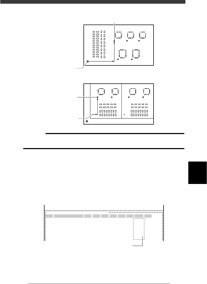
Local badmark XY coordinates
23615-C0-00
X
X
Y
Y
<Relative to PCB origin>
<Relative to block repeat No.1>
Badmark
Badmark
PCB origin
Block repeat
c
CAUTION
You can enter the XY coordinates of local badmarks by teaching. In this case, set the
PCB origin (block repeat) data correctly before teaching.
3 Open the Mount Info. screen and specify the badmark.
1. Press the [F3] key to display the edit item menu box, then select
“Mount Info.”.
2. Move the cursor to the data line for which you want to set the badmark
function, then enter the mark data No. you have registered in the Local
BadMrk Info., in the “BadMk” column of the selected data line.
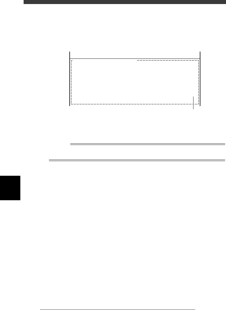
Local badmark settings
27623-C0-00
PCB :
SignOfLandPattern Comp X Y R Head FidMk BadMk
1
2
3
4
5
Skip?
OBJ :Mount Info.
No.
1
2
3
4
5
<<<APPLICATION>>> 2/DATA/M
<<MODE>> 1/EDIT_DATA
Enter one piece of local badmark data
for one piece of mount data.
6
-42
EPD8013110
Operation
Chapter 6
6
Using various functions
6
4 Open the PCB Info. screen and set the local badmark
function.
Press the [F3] key to display the edit item menu box again, then select
“PCB Info.” and set the “LocalBadmark” parameter to “Use”.
Setting the local badmark function on the PCB Info. screen
27624-C0-00
PCB :
LocalBadmark Use
OBJ : PCB Info.
<<<APPLICATION>>> 2/DATA/M
<<MODE>> 1/EDIT_DATA
Set to “Use”.
5 Save the data.
Press the [ESC] key to exit the current edit screen, then select <2/1/D8
SAVE PCB DATA> and press the [ENTER] key.
n
NOTE
The local badmark function can also be utilized for automatic switching of PCB types. See
“7. Self production control” for more details.