YV180X_Ope_E.pdf - 第248页
6 -13 EPD8013110 Operation Chapter 6 6 Using various functions Reconversion into the block repeat data 27608-C0-00 No. 1 2 3 4 5 X 0.00 30.00 0.00 30.00 Y 0.00 0.00 50.00 50.00 Block Comment BLOCK_1 BLOCK_2 BLOCK_3 BLOCK…
6
-12
EPD8013110
Operation
Chapter 6
6
Using various functions
2.2.2 Reconverting to the block repeat data
When editing or correcting one-block PCB data which was converted from
block repeat data, it will prove convenient to use the original block repeat
data. This section explains how to reconvert such data into the original
block repeat data. This data reconversion is possible only when the block
conversion was executed under “1: CONV. WITH NOTE DATA”.
1 Select <2/2/A1 OBJECT SELECTION> and press the [EN-
TER] key.
The OBJECT SELECTION menu box then appears.
2 Execute the PCB SELECTION command and select the PCB
name.
When a list of the registered PCB names appears, select the PCB to
execute reconversion, then select “QUIT” and press the [ENTER] key.
3 Select <2/2/A4 CONDITION SETTING> and press the
[ENTER] key.
The DATA GENERATOR CONDITION menu box then appears.
4 Select “BLOCK CONVERSION CONDITION” to set the
conditions.
When the submenu box appears, line up the cursor with “3: CONV. BACK
TO BLOCK” and press the [ENTER] key.
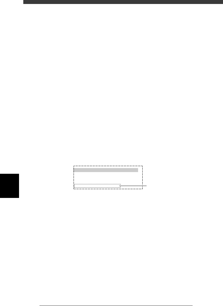
BLOCK CONVERSION CONDITION menu box
27607-C0-00
0: NO
1: CONV. WITH NOTE DATA
2: CONV. WITHOUT NOTE DATA
3: CONV. BACK TO BLOCK
BLOCK CONVERSION CONDITION
Move the cursor to this item
and press the [ENTER] key.
5 Set the “FEEDER SET CONDITION” parameter.
Set this parameter to “NO” when performing only the block reconversion.
Refer to “9.2 Setting optimization conditions” in Chapter 5 for more
details.
6 Execute the reconversion.
Press the [ESC] key to return to the <2/2/A/SETTING_&_RUN> menu
window, then select <2/2/A5 EXECUTE> and press the [ENTER] key. The
reconversion now starts.
6
-13
EPD8013110
Operation
Chapter 6
6
Using various functions
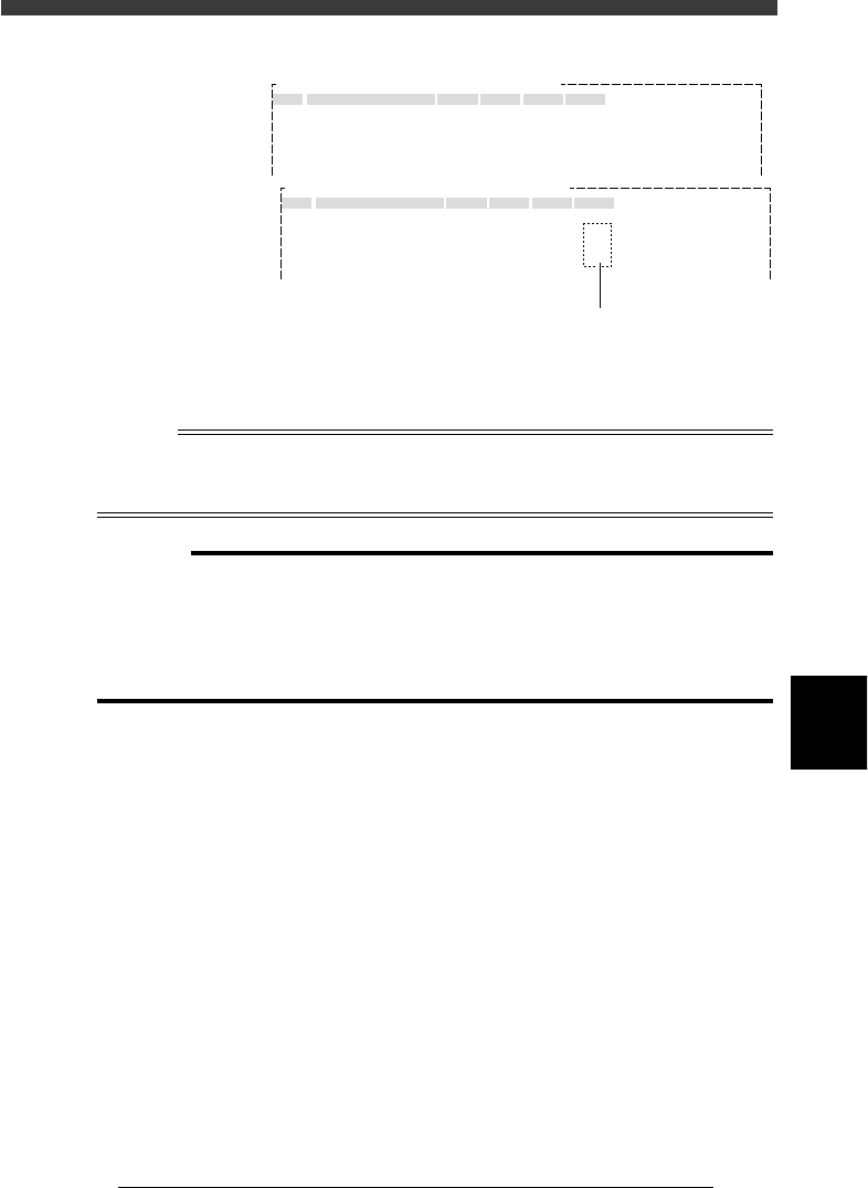
Reconversion into the block repeat data
27608-C0-00
No.
1
2
3
4
5
X
0.00
30.00
0.00
30.00
Y
0.00
0.00
50.00
50.00
Block Comment
BLOCK_1
BLOCK_2
BLOCK_3
BLOCK_4
Skip?
Exec
Exec
Exec
Exec
R
0.00
0.00
180.00
180.00
OBJ : Blk Repeat Info.PCB :
No.
1
2
3
4
5
X
0.00
30.00
0.00
30.00
Y
0.00
0.00
50.00
50.00
Block Comment
BLOCK_1
BLOCK_2
BLOCK_3
BLOCK_4
Skip?
Exec
Note
Note
Note
R
0.00
0.00
180.00
180.00
OBJ : Blk Repeat Info.PCB :
Before block conversion
Block repeat data remains as “Note” data.
After block conversion
7 Quit the command and save the data.
When the reconversion is complete, press the [ESC] key to quit the current
command, then select <2/2/B0 SAVE & EXIT> and press the [ENTER] key.
Reference
If you want to save the reconverted data with a name different from the block-converted
data (in other words, if you want to keep the block-converted data), use the <2/2/B5
RENAME & EXIT> command.
c
CAUTION
• The data once converted into single PCB data under “2: CONV. WITHOUT NOTE
DATA” cannot be reconverted back into the original data.
• Changes or corrections you have made to the single PCB data which was converted
from block repeat data will not be reflected in the reconverted data.
• If you delete or copy the “Note” data, it cannot be reconverted back into the original
block repeat data.

6
-14
EPD8013110
Operation
Chapter 6
6
Using various functions
3. Creating the user database
Registering components (or marks) in the user database will prove conve-
nient if they are not included in the YAMAHA database or used frequently.
The user database should be registered in the user area of the database in
the <2/3/DATABASE> mode. The user database area can be from Nos. 1 to
499 for the component database and from Nos. 1 to 149 for the mark
database. The registered data in this area will be retained even if the
software version is upgraded.
There are two methods for creating the user database: one by copying the
data from the component or mark information in <2/1/EDIT_DATA> mode
and the other by copying the data from the YAMAHA database.
n
NOTE
The database is a collection of sample settings for component data or mark data. The
software program installed in each machine contains the YAMAHA database which
includes sample settings for major standard components or marks, such as shapes and
recognition data. This is a powerful tool for creating your own database or actual mount
data. From the YAMAHA database, you can easily make a copy of component data or mark
data which is identical or similar to the components or marks you want to use. This
greatly saves the time and effort required for creating data. Normally, the YAMAHA
database is numbered from 500 to 1000 for components, and from 150 to 300 for marks.