YV180X_Ope_E.pdf - 第168页
5 -92 EPD8013110 Operation Chapter 5 5 Creating the PCB data 5 Enter “ PCB Fiducial ” . The PCB Fiducial settings correct the position of the entire PCB by using a pair of fiducial marks. When a pair of fiducial marks ar…
5
-91
EPD8013110
Operation
Chapter 5
5
Creating the PCB data
6.1 Creating procedure
1 Open the PCB Info. screen.
Select “PCB Info.” from the edit item menu box which appears after
registering or selecting a PCB name. If an edit screen is open, press the
[F3] key (or select <2/1/A1 MAIN WINDOW>) to display the edit item
menu box.
PCB Info. screen
27537-D8-00
PCB: OBJ :PCB Info.
MARK
1
1
1
6
X/X1
0.00
240.00
0.00
5.00
0.00
15.00
0
0
Y/Y1
0.00
175.00
10.00
5.00
0.00
5.00
0
0
MRK2
0
0
X2
1.6
230.00
215.00
Y2
160.00
77.50
Skip?
-1
NotUse
NotUse
NotUse
NotUse
Exec
NoCheck
IgnoreErr
PcbFixDevice
Pre-FixTimer
Trans-Height
Conv. Timer
Precede Pick
Pin+PushUP
0.00
0
0.00
Not Use
Local Fiduc.
LocalBadmark
Retry Seq.
TrayPrecede.
Sp.Function
Not Use
Not Use
Group
USe
Not Use
Mount
Vacuum Check
Aligment
PCB Origin
PCB Size
PCB Fiducial
BLOCK Fiducial
PCB Badmark
BLOCK Badmark
PCB Comment
Pcb/Schedule/Block
Unloader Count/Max
Operation condition
setting area
PCB parameters
2 Enter “PCB Origin”.
The PCB origin is the reference XY position on the PCB. Refer to “6.3 PCB
origin” in this chapter for more details.
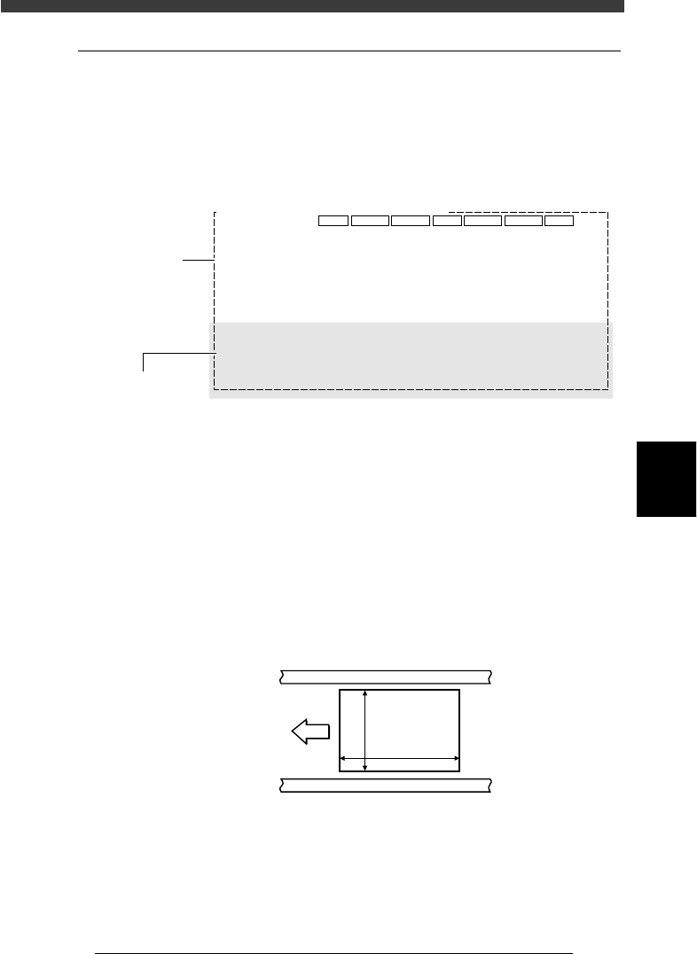
3 Enter “PCB Size”.
Enter the length of the PCB in the XY directions in millimeters. The
conveyor width (W-axis) will be adjusted according to the Y length in
automatic operation.
X coordinate: Length in the PCB flow direction
Y coordinate: Length in the conveyor width direction when the PCB is
set on the conveyor
PCB Size
23540-C0-00
X [mm]
Y [mm]
PCB
Direction of
PCB flow
4 Enter the thickness of the PCB.
Enter the thickness of the PCB in the “X2” column of the PCB Size.

5
-92
EPD8013110
Operation
Chapter 5
5
Creating the PCB data
5 Enter “PCB Fiducial”.
The PCB Fiducial settings correct the position of the entire PCB by using a
pair of fiducial marks. When a pair of fiducial marks are provided for the
entire PCB, make these settings as needed. Refer to “4. Using the fiducial
functions” in Chapter 5 to make the settings.
If you do not use this fiducial function, check that the Skip? column is set
to “NotUse” and advance to the next step.
6 Enter “BLOCK Fiducial”.
The BLOCK Fiducial settings correct the position of each block by using a
pair of fiducial marks. When a pair of fiducial marks are provided for each
block, make these settings. Refer to “4. Using the fiducial functions” in
Chapter 5 to make the settings.
If you do not use this block fiducial function, check that the Skip? column
is set to “NotUse” and advance to the next step.
7 Enter “PCB Badmark”.
The PCB Badmark settings determine whether to search for the badmark or
not. When PCBs with or without a badmark are fed on the conveyor, the
PCB badmark function shortens the production time. Refer to “5. Using the
badmark functions” in Chapter 5 to make the settings.
If you do not use this function, check that the Skip? column is set to
“NotUse” and advance to the next step.
8 Enter “BLOCK Badmark”.
The BLOCK Badmark settings determine whether to perform or to skip
component mount in each block. When you want to mount components
in some blocks, but not on other blocks, the block badmark function is
very useful. Refer to “50. Using the badmark functions” in Chapter 5 to
make the settings.
If you do not use this function, check that the Skip? column is set to
“NotUse” and advance to the next step.
9 Enter a comment in the PCB Comment.
You can enter a comment for the PCB in the Comment column as
necessary.
0 Specify “Pcb/Schedule/Block” for production.
In these columns, specify the PCB count when you want to specify the
quantity of PCB production. Enter a proper figure, referring to the descrip-
tion below.
• Pcb (X/X1)
The number of PCBs already produced is displayed in this column.
Set this to “0” as a start.
• Schedule (Y/Y1)
Enter the number of PCBs that you want to produce. When this is set
to “0”, the machine continues to produce PCBs as long as they are
fed on the conveyor.
• Block (X2)
Enter the number of blocks on a PCB. This setting is used as “BLOCK
NUMBERS” in <1/3/A2 PCB INF.>.
Reference
For details on the block settings, see “2. Using the block repeat function” in Chapter 6.

5
-93
EPD8013110
Operation
Chapter 5
5
Creating the PCB data
q Specify “Unloader Count/Max”.
In the Y/Y1 column of this parameter, specify the number of PCBs that can
be stored in one rack of the unloader. When the specified number of PCBs
has been produced and transferred out into the unloader, the machine
stops transfer of the production PCB until the unloader replaces the rack.
• Unloader Count
The number of PCBs transferred into the unloader is displayed in this
column. Set this to “0” as a start.
• Max
Specify the maximum number of PCBs that can be stored in one rack
of the unloader. If this is set to “0”, the machine continues production
without checking the number of PCBs transferred out into the
unloader. Enter “0” under the following conditions.
The unloader being used provides a rack switching signal output.
This setting data is to be used for the machine just before
reflowing.
w Set operating conditions.
Using the [Space], [INS] or [DEL] key, specify the necessary operating
conditions displayed on the lower half of the screen,
• Mount
Set to “Exec” to perform component mounting.
• VacCheck
Set this parameter to “Use”. Setting to “Use” allows the machine to
check whether components are being picked up during operation
based on the vacuum level, as well as checking with the vision
system.
• Alignment
Set to “UseAlign”. This setting allows the machine to check compo-
nent recognition during pickup.
• PcbFixDevice
Select the proper PCB clamping method according to the PCB to be
produced.
Locate Pin : A PCB is clamped on the conveyor only with the
locate pins.
Pin+PushUP : A PCB is clamped on the conveyor with the
locate pins and push-up pins. This is the most
accurate and preferred method.
Edge Clamp (option) : A PCB is clamped on the conveyor with
the edge clamps, push-in unit and push-up
pins, without using the locate pins.
• Pre-Fix Timer
The machine begins to clamp the PCB immediately after it passes
above the PCB sensor installed just before the main stopper. The
optimum clamping timing (delay time with respect to the sensor
detection) depends on the PCB size and conveyor speed.. Use this
parameter to set the clamp timing (0.0 to 1.9 sec.).