YV180X_Ope_E.pdf - 第93页
5 -17 EPD8008100 Operation Chapter 5 5 Creating the PCB data 1. BASIC INFO. parameters 1. Comp. Package Select the type of component feed. • T ape Select this setting when using a tape feeder which supplies compo- nents …
5
-16
EPD8008100
Operation
Chapter 5
5
Creating the PCB data
3.3 Chip components
3.3.1 Standard chip components
(box type chip resistors and capacitors)
Box type chip resistors and capacitors are registered with the parameters
shown below.
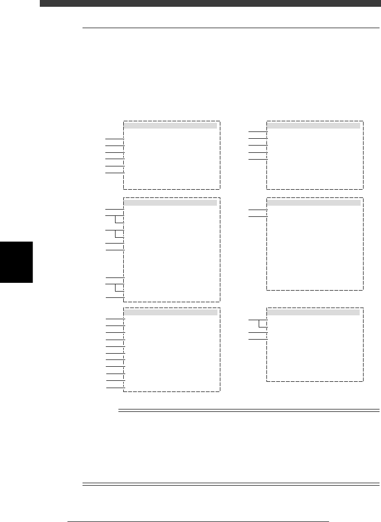
Chip component parameters
27510-D8-00
6. SHAPE INFO.
Body Size X mm
Body Size Y mm
Body Size Z mm
Ruler Offset
:
:
:
:
0.80
1.60
0.45
3
5. VISION INFO.
Alignment Group
Alignment Type
AlignmentModule
Light Selection
Lighting Level
Comp. Threshold
Comp. Tolerance
Search Area mm
Datum Angle
Comp. Intensity
MultiCam. Marker
:
:
:
:
:
:
:
:
:
:
:
Chip
Std.Chip
Fore&Back&Las
Main + Coax
6/8
Normal
NotUse
30
30
1.50
0
1. BASIC INFO.
Database No.
Comp. Package
Feeder Type
Required Nozzle
Feeder Set No.
Pos. Definition
Feeder Pos_X mm
:
:
:
:
:
:
:
Tape
8mmTape
For1608Chp72
Automatic
501
16
135.79
2. OPTION INFO.
FixCmpRef.
AIt.Cmp
Use feeder opt.
Comp. Group No.
Correct Pickpos
:
:
:
:
:
Yes
Not Use
0
0
0
3. PICK AND MOUNT INFO.
Pick Angle deg
Pick Timer
Mount Timer
Pick Height
Mnt Height
Pick Sequence
Mount Action
Mount Speed
PickupSpeed
XY Speed
Vacuum Check
Pick Vacuum
Mount Vacuum
Conv. Y Speed
:
:
:
:
:
:
:
:
:
:
:
:
:
:
4. DUMP INFO.
Dump Way
Retry Times
:
:
Dump POS
2
s
s
mm
mm
%
%
%
%
%
0
0.00
0.00
Normal
NORMAL
100
100
100
NORMAL CHK
FAST
0.0
0.2
30
30
1
2
3
4
5
6
11
12
13
14
15
31
32
61
62
63
21
22
23
24
25
26
27
28
29
41
42
43
44
45
46
47
48
49
50
51
n
NOTE
When setting the parameters shown in the sub-windows above, use the number keys to set
the parameters aligned on the right, while using the [INS], [DEL] or [Space] key to set
the parameters aligned on the left. However, there are some parameters which should be
set or optimized with the Adjust Assistant commands described later in “3.7” in this
chapter.
The displayed parameters differ slightly depending on the <3/1/A1 OPTION CONFIG>
settings.
5
-17
EPD8008100
Operation
Chapter 5
5
Creating the PCB data
1. BASIC INFO. parameters
1. Comp. Package
Select the type of component feed.
• Tape
Select this setting when using a tape feeder which supplies compo-
nents on paper tape, embossed tape or adhesive tape.
• Stick
Select this setting when using a stick feeder such as a single stick
feeder, multi-stick feeder, staked stick feeder and high-speed stick
feeder.
• Bulk
Select this setting when using a bulk cassette feeder.
2. Feeder Type
Select the specific feeder type to be used for component supply. Selectable
items differ depending on the Comp. Package setting. Refer to the table
below to make a selection.
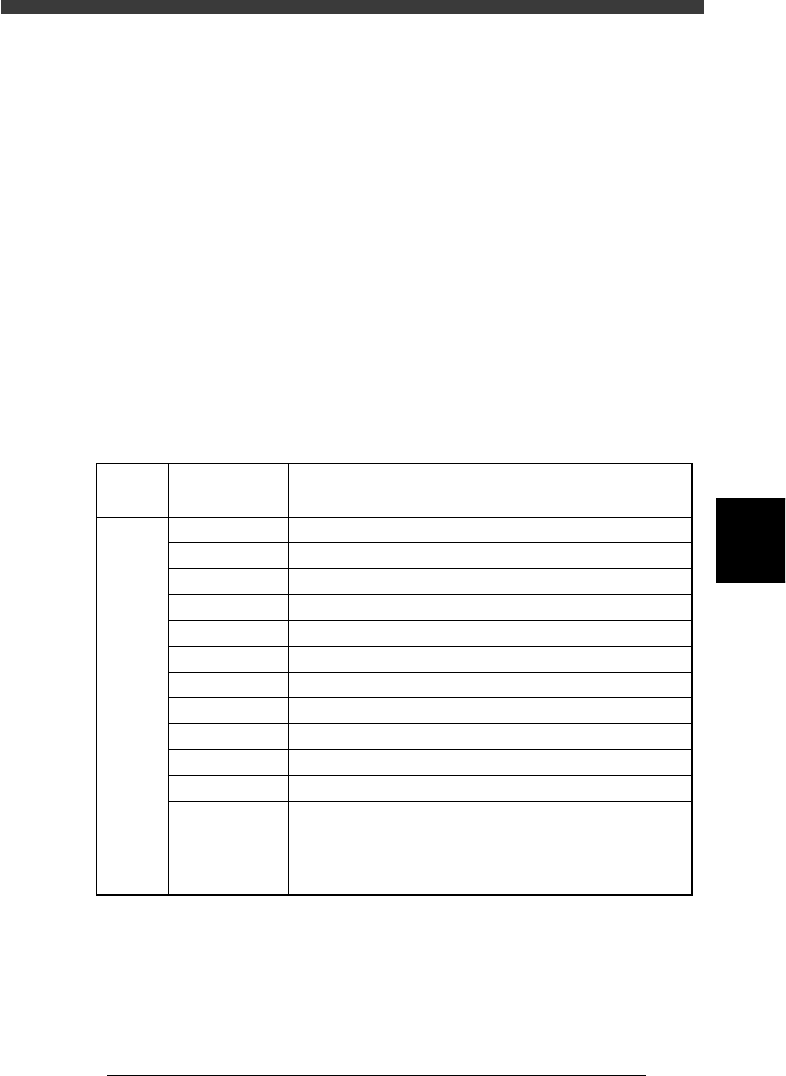
Feeder Type settings (when “Comp. Package” is set to “Tape”)
25501-C0-00
8mm tape feeder (except for 1005 chip)
8mm tape feeder (except for 0603 chip)
8mm tape feeder (for 1005 chip)
12mm tape feeder (standard pitch)
12mm tape feeder (long pitch)
16mm tape feeder
24mm tape feeder
32mm air-driven feeder with sticky tape
32mm embossed air-driven feeder
44mm embossed air-driven feeder
56mm embossed air-driven feeder
8mmTape
8mm 0603cmp
8mm1005cmp
12mmEmboss
12mmLongPitch
16mmEmboss
24mmEmboss
32mmSticky
32mmEmboss
44mmEmboss
56mmEmboss
Tape-A to D
Select these settings when using a tape feeder other than
the above. Note that you must make necessary settings on
the <3/1/B4 FEEDER SPEC. INF> screen.
For the setting procedure, refer to the mounter service
manual.
Comp.
Package
setting
Feeder Type
setting
Tape feeder or bulk cassette feeder type
Tape
5
-18
EPD8008100
Operation
Chapter 5
5
Creating the PCB data
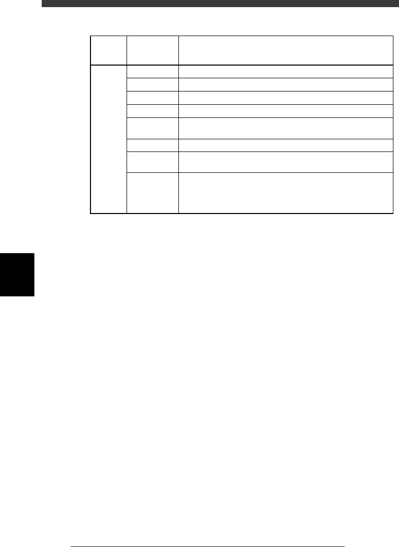
Feeder Type settings (when “Comp. Package” is set to “Bulk”)
25502-C0-00
Bulk-1005C
Bulk-1005R *
Bulk-1608C
Bulk-1608R *
Bulk-T0.6C
Bulk-T0.6R
Bulk-T1.25C
Bulk-A to D Select these settings when using a bulk feeder other than the
above. Note that you must make necessary settings on the
<3/1/B4 FEEDER SPEC. INF> screen.
For the setting procedure, refer to the mounter service manual.
Bulk feeder for 2125 capacitors (chip thickness 1.25mm). Marked
"2125 T1.25" on the feeder.
Bulk feeder for 2125 resistors. Marked "2125 T0.6" on the feeder.
Bulk feeder for 2125 capacitors (chip thickness 0.6mm). Marked
"2125 T0.6" on the feeder.
Bulk feeder for 1608 resistors. Marked "1608 R" on the feeder.
Bulk feeder for 1608 capacitors. Marked "1608 C" on the feeder.
Bulk feeder for 1005 resistors. Marked "1005 R" on the feeder.
Bulk feeder for 1005 capacitors. Marked "1005 C" on the feeder.
Comp.
Package
setting
Bulk
Feeder Type
setting
Tape feeder or bulk cassette feeder type
3. Required Nozzle
Select the optimum nozzle that matches the component size from among
the nozzle types for chip components. (See “Nozzle table” listed in the
supplement in this manual.)
4. Feeder Set No.
Enter the feeder set number of the position at which the feeder is installed.
This parameter setting is unnecessary when the Use feeder opt. parameter
is set to “Yes.”
5. Pos. Definition
Set to “Automatic” when you set the Comp. Package parameter to “Tape”
or “Bulk”. (The pickup position is automatically calculated.)
6. Feeder Pos_X
This parameter is skipped when the Pos. Definition parameter is set to
“Automatic”.
2. OPTION INFO. parameters
Some of these parameters are displayed only when the Simple Edition
parameter on the <3/1/A1 OPTION CONFIG.> screen is set to “Full
Items”.
11. FixCmpRef.
Set this parameter to “0” in normal operation. Enter static component
numbers here only when used. See “4. Static component information” in
Chapter 6 for more details.
12. Alt. Cmp.
This parameter specifies an alternative component number which can be
used if the current component runs out. When not needed to specify any
alternative component, leave it at “0”. For detailed information about