YV180X_Ope_E.pdf - 第24页
1 -14 EPD8013110 Operation Chapter 1 1 Par t names and functions Key functions 25103-C0-00 1 2 3 4 5 6 7 8 9 10 11 12 13 RUN STOP RESET ERROR READY JOY STICK SPEED SEL AXIS, AXIS GROUP TAB HELP F9 F10 INS, DEL Perform co…
1
-13
EPD8013110
Operation
Chapter 1
1
Part names and functions
5.1 YPU
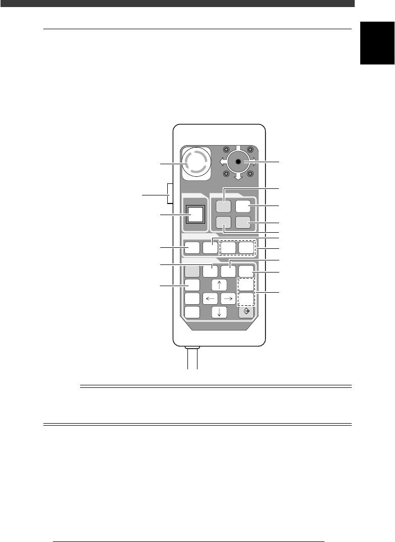
The YPU is a hand-held remote control device having easy-to-use functions
and command keys frequently used to operate the machine and edit the
machine data. The YPU also has an emergency stop button and a joystick
for axis movement in MANUAL mode. The illustration and table below
show the YPU key arrangement and functions.
YPU key arrangement
23107-C0-00
O
STOP
I
RUN
RESET
ERROR
CLEAR
JOY
STICK
AXIS
GROUP
SPEED
SEL
AXIS
HELP
ESC F9 F10
CTRL
DEL
TAB INS
SHIFT
ENTER
EMERGENCY STOP
SCREEN
MANUAL
READY RUNNING
4
1
2
3
5
6
9
10
13
12
11
8
7
Emergency stop button
[ACTIVE] key
Joystic
k
n
NOTE
The YPU keys are enabled only when the [ACTIVE] key on the left side of the YPU is
turned on. (The [STOP] and [ERROR CLEAR] keys and the emergency stop button can be
used regardless of whether the [ACTIVE] key is on or off.)
1
-14
EPD8013110
Operation
Chapter 1
1
Part names and functions
Key functions
25103-C0-00
1
2
3
4
5
6
7
8
9
10
11
12
13
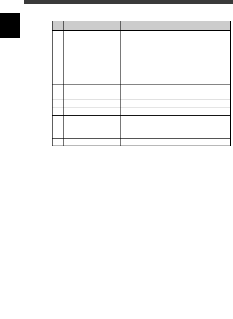
RUN
STOP
RESET
ERROR
READY
JOY STICK
SPEED
SEL AXIS, AXIS GROUP
TAB
HELP
F9
F10
INS, DEL
Perform component mount according to PCB data.
Interrupt automatic operation.
(Press RUN to resume operation.)
Stop automatic operation and return to standby
state for PCB production.
Stop buzzer sound and clear error screen.
Release emergency stop and turn the servo on.
Move the axis manually.
Switch speed in 5 steps.
Select the axis.
Move the cursor between the right and left windows.
Display the help message for the selected item.
Perform tracing.
Perform teaching.
Switch parameter setting on the screen or sub-window.
Key name Use the key to:
1
-15
EPD8013110
Operation
Chapter 1
1
Part names and functions
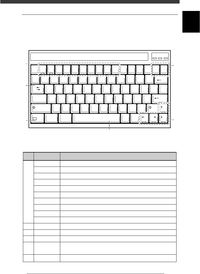
5.2 Keyboard
A keyboard is supplied with each machine as a standard accessory for
machine operation and data editing. The keyboard arrangement and
functions are explained below.
Keyboard arrangement
21101-C0-00
EscF1F2F3F4F5F6F7F8F9F10
Num
Lock
Prt Sc
SysRq
Scroll
Lock
Pause
Break
Insert Delete
Backspace
QWERT YU I OP
ASDFGHJKL
ZXCVBNM
~
`
!
1
@
2
#
3
$
4
%
5
^
6
&
7
*
8
(
9
)
0
_
-
+
=
{
[
}
]
|
\
:
;
"
'
?
/
<
,
>
.
Tab
CapsLock
Shift
Shift
Ctri Alt
Alt Ctri
Enter
Fn
F11 F12
PgUp
PgDnEndHome
Num Caps Scroll
1
3
2
6
5
4
Key function
25104-C0-00
1
2
3
4
5
6
F1
F2
F3
F4
F5
F6
F7
F8
F9
F10
Insert, Delete
Tab
↑ ↓ ← →
Space Bar
Fn
Display the help message for the selected item.
Switch the production PCB.
Switch the edit object. (PCB Info., Component Info., Mount Info. etc.)
Switch the sub-window. (USER ITEMS, SHAPE, VISION, etc.)
Make the cursor jump to the data address.
Execute the Adjust Assistant command.
Set the database.
Display the silhouette on the vision monitor.
Perform tracing.
Perform teaching.
Switch parameter settings on an editing screen or sub-window.
Move the cursor between right and left windows.
Move the cursor in the indicated direction or page up/down.
Switch parameter setting on an editing screen or sub-window.
Pause the machine during operation. Press again to release.
Allow special function while pressing another key. ([Fn]+[↑] for Page Up, etc.)
Key name Use the key to: