YV180X_Ope_E.pdf - 第140页
5 -64 EPD8013110 Operation Chapter 5 5 Creating the PCB data 3. Press the [T AB] key to return to the Adjust Assistant screen and run the P ARAM SEARCH command. The P ARAM SEARCH command automatically finds and enters th…
5
-63
EPD8013110
Operation
Chapter 5
5
Creating the PCB data
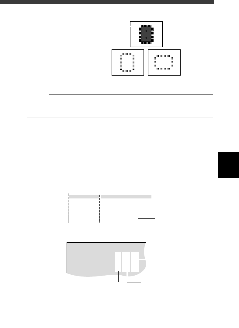
Component image and outline definition
23521-C0-00
9632 Z00
Component image taken
with the VISION TEST
command
Component outline
displayed with the DRAW
THE SHAPE command
NGOK
n
NOTE
To check the outline definition of a component which is recognized with a multi-vision
camera, use the image recognized when the component passes over the camera from left to
right as the reference.
2. Check the parameters in the SHAPE INFO. sub-window.
To make this check, set the Monitor Mode in the Adjust Assist Items
window to “Result” and then perform the VISION TEST command
again. The recognition results will be displayed on the upper left of the
vision monitor. Press the [TAB]key to move the cursor to the right-hand
sub-window. Then check if the parameter settings in the SHAPE sub-
window such as “Body Size” and “Lead Number” match the results
obtained. Correct the settings as necessary.
Monitor Mode setting
27527-C0-00
Comp Name :
Command Adjust Assist Items
Monitor Mode Result
Set here
Monitor Mode display on the vision monitor
27528-C0-00
XC,YC
North
South
West
East
:
:
:
:
:
290.3
X
263.0
253.7
131.1
387.1
385.4
Y
185.4
584.0
381.6
389.1
N:100
N
20
20
30
30
R:
pit
0.66
0.66
0.64
0.64
1.56
wild
0.36
0.35
0.32
0.33
,
Lead widt
h
Lead pitch
Number of leads

5
-64
EPD8013110
Operation
Chapter 5
5
Creating the PCB data
3. Press the [TAB] key to return to the Adjust Assistant screen and run the
PARAM SEARCH command.
The PARAM SEARCH command automatically finds and enters the
optimum values for the component parameters.
Parameters optimized with the PARAM. SEARCH command
27529-C0-00
THRESHOLD
LIGHTING LEVEL
SEARCH AREA
F. LINE OFFSET
35
6/8
5.00
3
(mm)
4. Run the VISION TEST command again. Repeat this test several times. If
there is no error, the adjustment is complete. Return the Monitor Mode
setting in the Adjust Assist Items window to “Nothing”.
0 Discard the component.
To discard the component at dumping position, run the DISCARD COMP.
command.
If you do not want to dump the component, follow the procedure below.
1. Run the PICK UP COMP. command.
e
2. When the head stops completely at the component pickup position,
press the emergency stop button and remove the component by hand
from the nozzle.
3. Run the DISCARD COMP. command to stop vacuum generation.
q Quit the Adjust Assistant.
Select the EXIT command and you will return to the Component Info.
screen.

5
-65
EPD8013110
Operation
Chapter 5
5
Creating the PCB data
3.8 Setting the stick feeder component
data
When using stick feeder components (multi or single stick feeders), you
must enter the following settings in the component information.
3.8.1 When optimizing the feeder set positions
To determine the feeder set positions by data optimization (automatic
search for optimum feeder set positions), follow these steps.
1 Set the stick feeder on the feeder plate.
Install the stick feeder with components loaded on the feeder plate, at a
position that meets the following two conditions.
1. Within the working range of the moving camera
The moving camera is used for teaching of the component pickup
point.
2. On the front feeder plate
The component information is specified based on the component
supply from the front feeder plate.
Reference
For details on how to load components into a stick feeder or set a stick feeder on the
feeder plate, refer to the separate feeder user’s manual.
2 Select the component data.
Move the cursor to the data line of the component which is supplied by
the stick feeder.
3 Set the “Comp. Package” parameter in the BASIC INFO.
sub-window to “Stick”.
1. Press the [TAB] key to move the cursor into the BASIC INFO. sub-
window on the Component Info. screen. If the BASIC INFO. sub-
window is not displayed, press the [F4] key to switch the sub-window
display.
2. Align the cursor with “Comp. Package” and press the [INS], [DEL] or
[SPACE] key to set this parameter to “Stick”.