YV180X_Ope_E.pdf - 第296页
6 -61 EPD8013110 Operation Chapter 6 6 Using various functions Upper left corner start (stationary) point: The window can be enlarged or reduced with the arrow keys, using the upper left corner of the window as a start p…
6
-60
EPD8013110
Operation
Chapter 6
6
Using various functions
6
4 Execute the Adjust Assistant.
Press the [F6] to open the Adjust Assistant screen. Adjust the image
processing parameters with the procedure below in order to obtain a clear
image of the target pattern.
Example of pattern image taken with the Adjust Assistant command
27638-C0-00
FIX PCB
TEACH MARK
VISION TEST
PARAM. SEARCH
SAVE PATTERN
DISP. PATTERN
CHK THRESHOLD
EXIT
Mark Threshold
Tolerance
Search Area
Pattern Number
Pattern Size X
Pattern Size Y
Offset X
Offset Y
(%)
(mm)
129
30
3.00
0
0
0
1.77
4.71
Mark Name : patern
Adjust Assist ItemsCommand
1. Using the FIX PCB command, clamp the PCB you want to use for
pattern matching on the conveyor of the mounter. (For details refer to
“4.3 Executing the Adjust Assistant” in Chapter 5.)
2. Execute the TEACH MARK command and operate the joystick so that
the pattern is displayed in the center of the vision monitor.
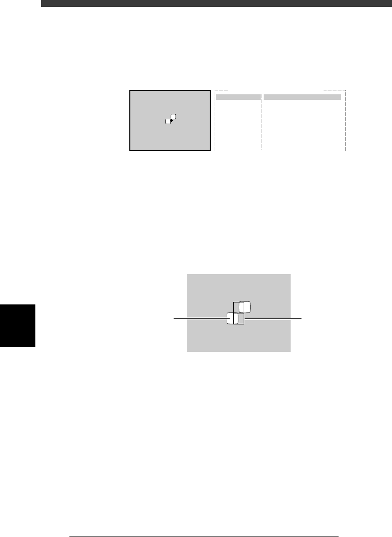
5 Execute the SAVE PATTERN command.
The following screen appears on the vision monitor when the SAVE
PATTERN command is executed.
Pattern registration screen
23624-C0-00
X.Y : 220.205
Size : 71.101
Off : 35.50
Pattern
Windo
w
6 Decide on the pattern size.
Following the message “Please teach template size and position. (Step 1)”
displayed on the operation monitor, enclose the pattern with a square
window by using the [TAB] key and arrow keys. Adjust and determine the
window size and position as explained below, then press the [ENTER] key.
The area enclosed with the window is registered as a template.
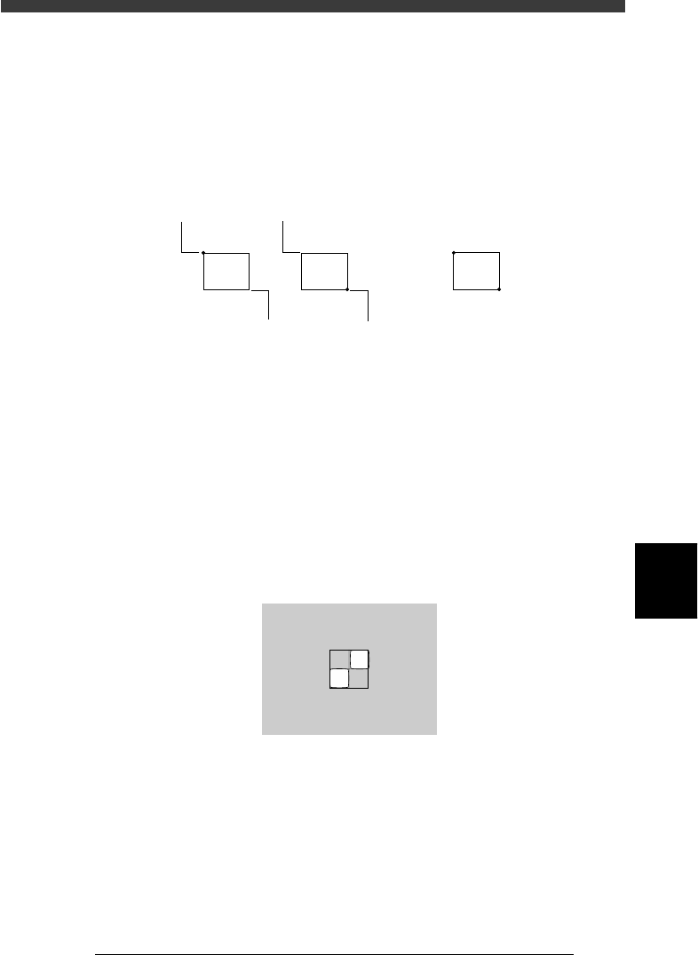
[TAB] key
Each time you press the [TAB] key, the start point (stationary point) of
the window changes to “lower right corner” → “upper left corner” →
“center”. Select the starting point with which you can enclose the
pattern easily.
Lower right corner start (stationary) point:
The window can be enlarged or reduced with the arrow keys, using
the lower right corner of the window as a start point. However, the
window cannot be expanded further right or downwards of the start
point.
6
-61
EPD8013110
Operation
Chapter 6
6
Using various functions
Upper left corner start (stationary) point:
The window can be enlarged or reduced with the arrow keys, using
the upper left corner of the window as a start point. However, the
window cannot be expanded further left or upwards of the start
point.
Center:
The entire window moves with the arrow keys.
Changing the window size and position
23625-C0-00
Moving point
Moving point Start (stationary) point
Start (stationary) point
Entire window moves
Arrow keys
When the lower right or upper left start point is selected, pressing an
arrow key changes the window size. When the center point is selected,
pressing an arrow key moves the entire window. If you press an arrow
key while holding down the [SHIFT] key, the entire window moves to
larger distance.
[ESC] key
Press the [ESC] key if you want to cancel pattern registration.
[ENTER] key
Press the [ENTER] key when the pattern size and position have been
determined, and advance to the next step.
Pattern size adjustment
23626-C0-00
X.Y:134.181
Size
Off
:
:
150.
127.
147
73
6
-62
EPD8013110
Operation
Chapter 6
6
Using various functions
6
7 Teach the center of the pattern.
1. Following the message “Please teach the template center. (Step 2)”,
align the center of the window (template) with the center of the pattern
and then press the [ENTER] key. If they are already aligned, just press
the [ENTER] key.
2. The message “Do you want to save this template?” then appears. Press
the [ENTER] again to save the pattern. If you do not want to save it,
press the [ESC] key.
Reference
If the pattern size is too large, a “template size error” may occur. In this case, redo the
procedure from Step 6.
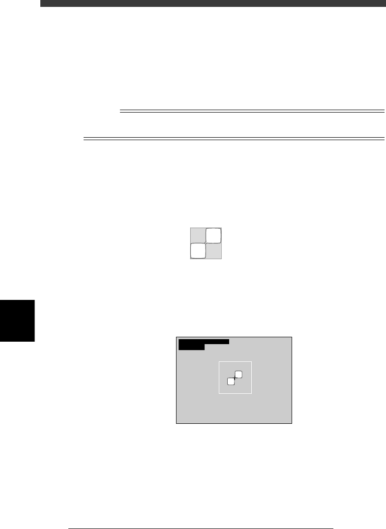
8 Check the image.
Execute the DISP. PATTERN command when registration is complete. The
image of the pattern enclosed by the window is displayed on the upper left
of the vision monitor. If an acceptable image cannot be obtained, redo the
procedure from Step 6.
Pattern display
21602-C0-00
Size
Offset
FileSize
:
:
:
190,
95.0
17322
147
74.0
9 Execute the VISION TEST command.
Check that the pattern is correctly recognized by executing the VISION
TEST command. Repeat this test several times. If the pattern can be
reliably detected, then the setting is okay.
VISION TEST screen for mark recognition
21603-C0-00
XC
mat
:
:
256.1
1.00
YC:255.9