YV180X_Ope_E.pdf - 第156页
5 -80 EPD8013110 Operation Chapter 5 5 Creating the PCB data Mark Size Info. Parameters 8. Mark OutSize Referring to the table below , enter the correct value in the MarkOutSize column in the Mark Size Info. sub-window .…
5
-79
EPD8013110
Operation
Chapter 5
5
Creating the PCB data
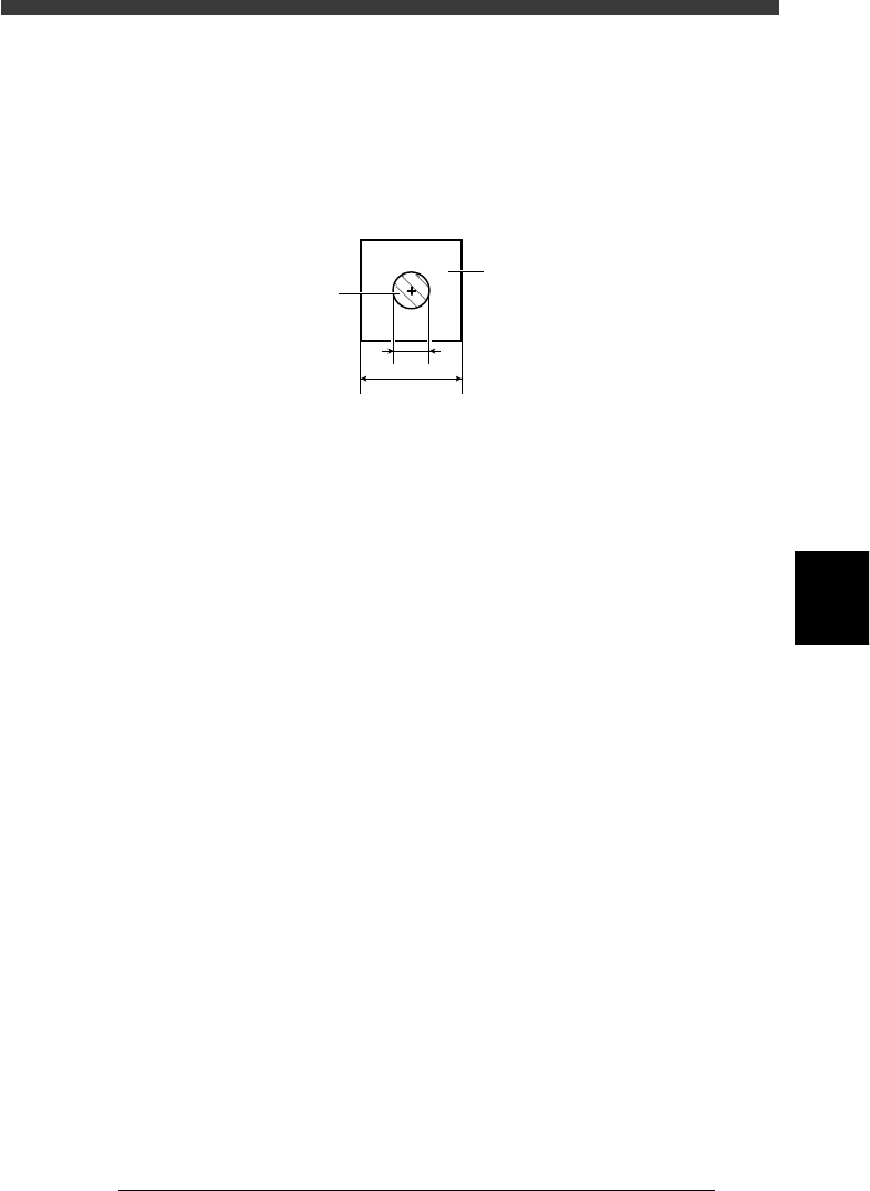
6. Search Area
It is recommended that this parameter be set to the mark diameter plus
3mm. For example, when the mark diameter is 1mm, set this parameter to
“4mm” as shown below.
If other marks (such as resist, screen print, other patterns) exist in this
search area, make the Search Area setting smaller.
Search Area
23531-C0-00
1
4
Search Area
Mark
7. Sequence
This parameter appears only when the Option Edit parameter on the <3/1/
A1 OPTION CONFIG.> menu is set to “EXIST”. There are 3 choices:
“Normal”, “Quick” and “Fine”. Select “Quick” when the cycle time is
more important, but select “Fine” when accuracy is more important.
5
-80
EPD8013110
Operation
Chapter 5
5
Creating the PCB data
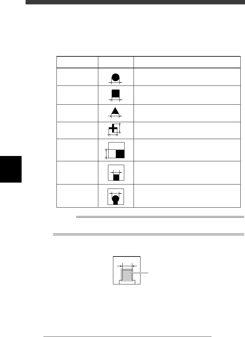
Mark Size Info. Parameters
8. Mark OutSize
Referring to the table below, enter the correct value in the MarkOutSize
column in the Mark Size Info. sub-window.
Mark OutSize settings
25514-C0-00
Example MarkOutSize settingShape type
Circle
Square
Triangle
Sp. Shape
Corner
TopEdge
CirEdge
Enter the diameter.
Enter the length of one side.
Enter the length of one side.
Enter the X length for the MarkOutSize X, and
the Y length for the MarkOutSize Y.
Enter the length of the shorter side displayed
within the search area.
Enter the length of the shortest side from among
the three sides displayed within the search area.
Enter the diameter of the round edge.
X
Y
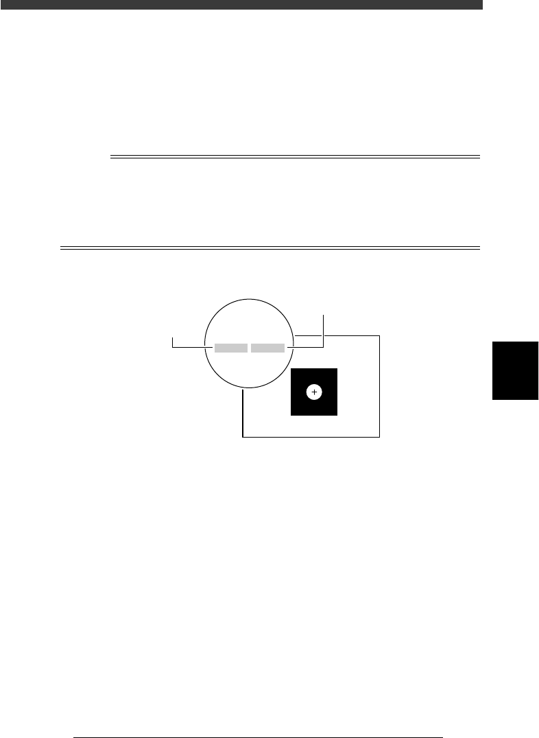
Reference
If you use a special mark with two or more edges as shown below, enter the size of the
shortest side of the rectangular area you want to detect
Mark OutSize setting for special mark
23532-C0-00
Rectangular area
to be detected
5
-81
EPD8013110
Operation
Chapter 5
5
Creating the PCB data
9. Mark Area
Enter here the area of the mark in units of square millimeters. This
parameter is displayed only when the Shape Type in the Vision Info. sub-
window is set to “Sp. Shape”.
10. Perimeter
Enter here the perimeter length of the mark in units of millimeters.
This parameter is displayed only when the Shape Type in the Vision Info.
sub-window is set to “Sp. Shape”.
n
Note
A recognition error may occur due to environmental conditions such as illumination. In
such cases, enter a larger value than previously used for the “Tolerance” parameter in the
Vision Info. sub-window, or set the tolerance to 100%, then perform “VISION TEST” in
the Adjust Assistant and enter the obtained data on the area and perimeter. (The mark
area and perimeter values are displayed after VISION TEST as shown below.) Return the
tolerance to the original value after the data is obtained.
Mark area and perimeter display
23533-C0-00
XC:257.2
area:0.74
YC:258.7
peri:3.21
XC:257.2
area:0.74
YC:258.7
peri:3.21
Perimeter
Area