YV180X_Ope_E.pdf - 第281页
6 -46 EPD8013110 Operation Chapter 6 6 Using various functions 6 6. On the vision monitor , you will see a square window with the length of one side specified by the “ Search Area ” parameter in the V ision Info. sub-win…
6
-45
EPD8013110
Operation
Chapter 6
6
Using various functions
4. When the position is selected, press the [ENTER] key.
The threshold level for detecting the area with no mark is entered as
the LEVEL 1 on the Adjust Assistant screen. The message then changes,
asking you to perform teaching at the badmark position. Manipulate the
YPU joystick so that the cross cursor on the vision monitor is aligned
with the badmark affixed on the PCB.
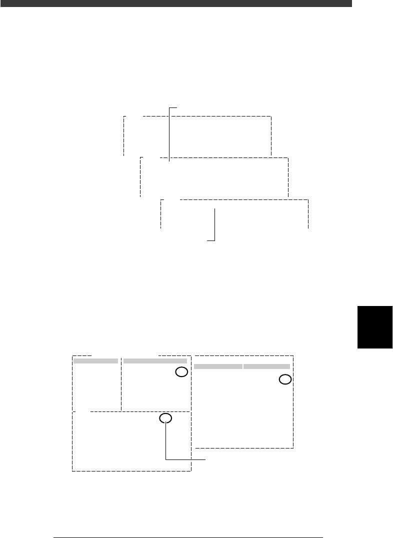
Threshold level teaching screens (for badmark)
27628-C0-00
V196
(LEVEL 1= LEVEL 2= RESULT= )
Please teach badmark as detected. (1st)
Hit [ENTER] to finish teaching.
When you move table or head,
Be careful for safety !!!
V197
(LEVEL 1=20 LEVEL 2= RESULT= )
Please teach badmark as detected. (2nd)
Hit [ENTER] to finish teaching.
When you move table or head,
Be careful for safety !!!
V200
(LEVEL 1= 20 LEVEL 2=118 RESULT= 80 )
PARAM. SEARCH for mark succeeded.
Threshold level when no mark is detecte
d
Threshold level when mark is detected
5. When the badmark is positioned in the center of the vision monitor,
press the [ENTER] key.
The threshold level of the badmark is now measured and entered as the
LEVEL 2. At the same time, the mid value between the LEVEL 1 and
LEVEL 2 is entered as the RESULT value. This value is used as the
optimum threshold level when detecting the badmark.
PARAM. SEARCH command screen (for badmark)
27629-C0-00
Mark Threshold
Vision
Edit Term
Mark Threshold
Info.
V200
(LEVEL1= 20 LEVEL2=118 RESULT= 69 )
PARAM. SEARCH for mark succeeded.
Mark Name: BADMARK
Command Adjust Assistant Items
69
69
:
:
Mid value between LEVEL 1 and
LEVEL 2 is calculated and reflected
on "Mark Threshold" value.
6
-46
EPD8013110
Operation
Chapter 6
6
Using various functions
6
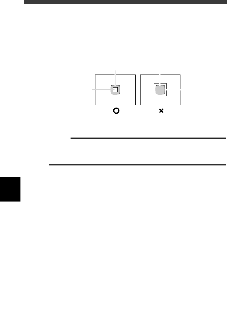
6. On the vision monitor, you will see a square window with the length of
one side specified by the “Search Area” parameter in the Vision Info.
sub-window. Since the average brightness in this square window is
measured to determine the badmark threshold level, the square
window must be positioned within the badmark. If the square window
is larger than the badmark, reduce the “Search Area” parameter value
in the Adjust Assist Items.
Badmark detection area (Search Area)
23617-C0-00
Badmark
Mark search
area
Badmark
Mark search
area
4 Execute the EXIT command.
Exit the Adjust Assistant and return to the Mark Info. screen.
n
NOTE
When you quit the Adjust Assistant, the optimized result (“Mark Threshold” value) will
automatically be entered for the “Mark Threshold” parameter on the Vision Info. sub-
window in the mark information. For more details on threshold levels, see “4.3 Executing
the Adjust Assistant commands” in Chapter 5.
6
-47
EPD8013110
Operation
Chapter 6
6
Using various functions
7. Self production control
Self production control allows the machine to identify specified PCBs by
recognizing the mark on the PCB, from among different types of PCBs
which are consecutively supplied on the conveyor.
For example, when you want to mount different components between the
front and back sides of a PCB, affix badmark A to the front side and
badmark B to the back side, and register their information in the Mark Info.
and also Local Badmark Info. Then, register the mount data on both sides
of the PCB in the Mount Info. and specify badmark A in the “BadMk”
column of components to be mounted on the front surface, while specify-
ing badmark B in the “BadMk” column of the components to be mounted
on the back side. With these settings, even when PCBs are supplied with
either the front or back side facing up, the machine identifies the front and
back sides, and mounts components only on the front side when badmark A
is recognized. Likewise, the machine mounts components only on the back
side when badmark B is recognized.
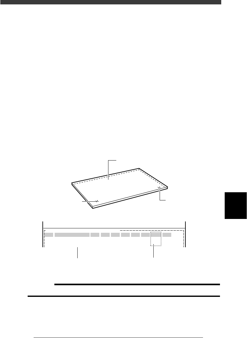
Badmarks for self production control
23618-C0-00
PCB :
SignOfLandPattern
R1005
R2125
Comp
10
12
BadMk
1
2
Skip?
Exec
Exec
OBJ :Mount Info.
No.
1
2
<<<APPLICATION>>> 2/DATA/M
<<MODE>> 1/EDIT_DATA
X
30.00
20.50
Y
45.00
10.00
R
0.00
0.00
Head
1
2
FidMk
0
0
Front or back side of PCB can be
identified by badmark No. setting
Front side badmark (A)
Back side badmark (B
)
Register the mount data for
both front and back sides
PCB
c
CAUTION
Self production control can only be used for PCBs with the same size.