YV180X_Ope_E.pdf - 第147页
5 -71 EPD8013110 Operation Chapter 5 5 Creating the PCB data 3.9 Registration location of component data Component data can be registered in the “Component Info.”, “Component Database” and “ST A TIC COMPONENTS” informati…

5
-70
EPD8013110
Operation
Chapter 5
5
Creating the PCB data
7 Perform teaching for the pickup position.
Referring to the procedure below, perform teaching for the coordinates of
the pickup position for a component.
1. Move the cursor to “Feeder Pos_X mm”.
2. Manipulate the YPU joystick to move the camera directly above the
component to be picked up.
Making sure that the cross cursor on the vision monitor is positioned at
the center of the component, press the [F10] key twice to perform
teaching.
The teaching position coordinates relative to the machine origin have
now been entered.The teaching conditions should be set as follows:
Teaching unit : Select “camera”
Speed : Select a slow speed (SPEED=20 to 40).
Fiducial : Select “NotUse”.
8 Set the Use feeder opt. parameter in the OPTION INFO.
sub-window to “No”.
Use the [INS], [DEL] or [SPACE] key to set this parameter to “No”.
n
NOTE
When the stick feeder needs to be installed at a particular position, you cannot make off-
line settings. Be sure to use teaching to enter the correct pickup point.
5
-71
EPD8013110
Operation
Chapter 5
5
Creating the PCB data
3.9 Registration location of component
data
Component data can be registered in the “Component Info.”, “Component
Database” and “STATIC COMPONENTS” information. To create PCB
data more efficiently, it is important to register the component data in the
appropriate location by considering how the component is to be used. Refer
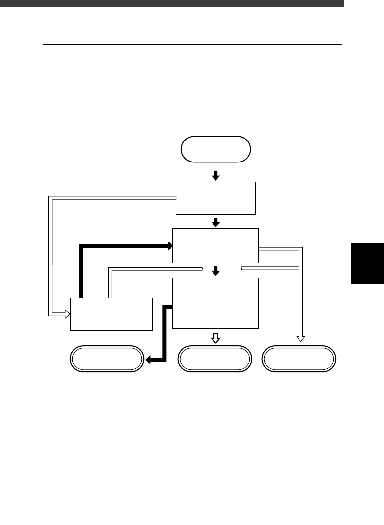
to the following flow chart when determining the registration location.
Flow chart for determining component registration location
23527-C0-00
START
Is the same type of
component registered
in YAMAHA database?
Do you use this component
in different PCB
production?
Do you want to save this
data along with various
parameter settings?
Do you want to change
component setup ?
STATIC_COMPONENT
information
Component database Component Info.
YES
YES
YES
NO
NO
NO
NO
YES
5
-72
EPD8013110
Operation
Chapter 5
5
Creating the PCB data
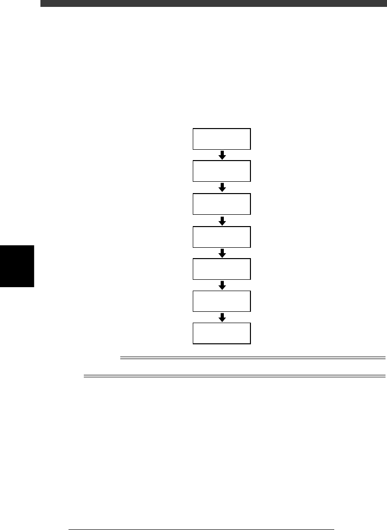
4. Creating the mark information
This section describes how to create mark information for fiducial marks
used on a PCB. Mark information has various parameters for each of the
mark names registered. To set these parameters, copy sample data of a
mark with a similar shape from the database and edit only the different
parameters.
Flow chart for creating mark information
23528-C0-00
4.2
☞
4.3
☞
Open
Mark Information
Enter COMMENT
Enter MARK
NAME
Copy database
information
Set various
parameters
Execute Adjust
Assistant
Save data
Reference
To create mark information on badmarks, see “6. Using badmark functions” in Chapter 6.