YV180X_Ope_E.pdf - 第116页
5 -40 EPD8008100 Operation Chapter 5 5 Creating the PCB data 5. VISION INFO parameters 41. Alignment Group Set this parameter to “ IC ” . 42. Alignment T ype Set this parameter to “ QFP ” with the [INS], [DEL] or [Space]…

5
-39
EPD8008100
Operation
Chapter 5
5
Creating the PCB data
c
CAUTION
Pickup angle setting directly affects the recognition reference and mounting angle. Be
careful not to mistake 0° for 180° for horizontally long components in the loading
position and 90° for -90° for vertically long components.
22. Pick Timer, Mount Timer
Refer to the description in “3.4.2 SOP component”.
23. Pick Height, Mount Height
Refer to the description in “3.3.1 Standard chip components”.
24. Pick Sequence
Refer to the description in “3.3.1 Standard chip components”.
25. Mount Action
Set this parameter to “QFP” when mounting accuracy is more important
than operation speed. (“FINE” is invalid for the YV180X.)
When “DETAIL” is selected here, several sub-parameters appear for
selecting or editing the optimal mouonting speed and accuracy.
26. Vacuum Check
Set this parameter to “SPECIAL CHK” in most cases because QFP
components should be checked more strictly for pickup and mounting
errors than other components.
n
NOTE
This parameter setting is valid only when the Vacuum Check parameter on the PCB Info.
screen is set to “Check”.
27. Pick Vacuum, Mount Vacuum
These are reference vacuum pressures used for checking the pickup and
mount vacuum levels. Use the default settings and adjust them as needed
in the Adjust Assistant mode. (See “3.7” in this chapter.)
28. Conv. Y Speed
Refer to the description in “3.3.1 Standard chip components”.
4. DUMP INFO. parameters
31. Dump Way
Set to “Station” when a QFP dump station (option) is used and to “Dump
POS” when not used. Refer to the Discard point parameter explained in the
mounter service manual.
32. Retry Times
Refer to the description in “3.3.1 Standard chip components”.

5
-40
EPD8008100
Operation
Chapter 5
5
Creating the PCB data
5. VISION INFO parameters
41. Alignment Group
Set this parameter to “IC”.
42. Alignment Type
Set this parameter to “QFP” with the [INS], [DEL] or [Space] key.
43. AlignmentModule
This parameter specifies the lighting method for recognizing a component.
Use the default setting (Fore&Back) in most cases. Refer to the description
in “3.3.1 Standard chip components” for more details.
For descriptions of the following VISION INFO. parameters, refer to
“3.3.1 Standard chip components”.
44. Light Selection
45. Lighting Level
46. Comp. Threshold
47. Comp. Tolerance
48. Search Area
49. Datum Angle
50. Comp. Intensity
51. MultiCam. Marker
6. SHAPE INFO. parameters
Set these parameters after specifying the VISION INFO. parameters. If
“Alignment Type” is undefined, the following parameters are not dis-
played.
61. Body Size X, Body Size Y
Enter the correct dimensions including the leads, measured with a vernier
caliper or micrometer.
62. Body Size Z
Enter the correct thickness measured with a vernier caliper or micrometer.
63. Ruler Offset
Refer to the description in “3.4.1 Mini-mold transistors/SOT”.
64. Ruler Width
Refer to the description in “3.4.1 Mini-mold transistors/SOT”.
65. LeadNumber
Enter the number of leads existing in the N and E directions. For the
component direction, see “K Pick Angle deg.”.
66. ReflectLL
Enter the projected length of leads which reflect light during recognition.
Use the default setting in most cases.
67. LeadWidth
Enter the correct lead width.
5
-41
EPD8008100
Operation
Chapter 5
5
Creating the PCB data
68. LeadPitch
Enter the correct lead pitch (lead-to-lead spacing).
69. Bumper Mask
This parameter is used for QFPs with bumpers. Enter the distance in
millimeters from the cross point of the ruler lines, in order to specify the
area by which bumpers are masked and not detected during component
recognition. Enter “0.00” for normal QFPs with no bumpers.
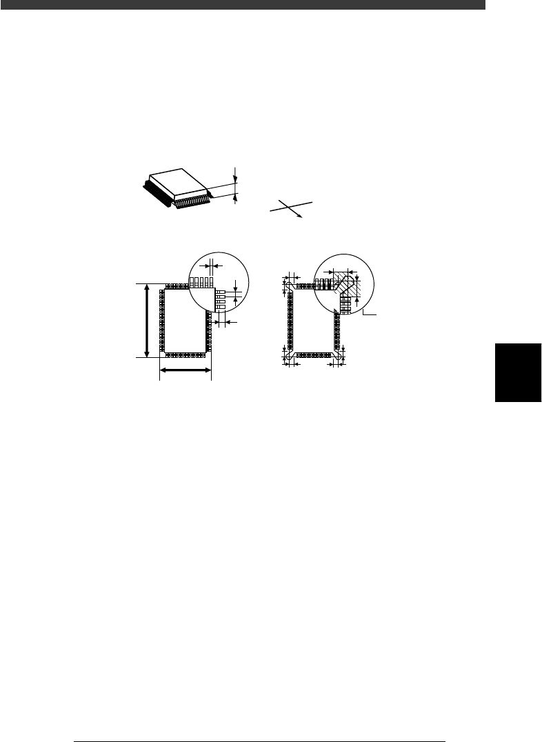
SHAPE INFO. parameters for QFP
23514-C0-00
A
S
E
W
N
C
B
G
G
E
D
F
A : Body Size Z
B : Body Size X
C : Body SizeY
D : Reflect LL
E : LeadPicth
F : LeadWidth
G: Bumper Mask
This area is
not detected
Bottom view
G
G
G
G
G
G