YV180X_Ope_E.pdf - 第35页
3 -4 EPD8013110 Operation Chapter 3 3 Manual operation 1.2 Selecting the axis T o use the joystick, you should first check or select the axis you want to use. 1 Enter MANUAL mode. 2 Press the [SEL AXIS] or [AXIS GR OUP] …
3
-3
EPD8013110
Operation
Chapter 3
3
Manual operation
1. Using the joystick
In MANUAL mode you can manipulate the joystick to move a servomotor-
controlled unit along its axis. (See “5.1” in Chapter 1 for the YPU func-
tions.)
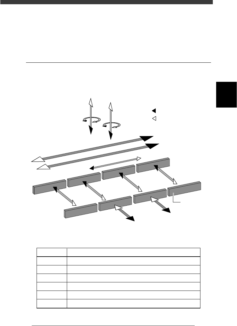
1.1 Axis configuration
The machine axis configuration and operation are shown in the drawing
and table below.
Axis configuration and plus/minus directions
23301-D8-00
W1-axis
Y2-axis
(B teble)
Y1-axis
(A table)
Z2-axis
R2-axis
Plus direction
Minus direction
X2-axis
X1-axis
T-axis
Conveyor rail
W2-axis
W3-axis
W4-axis
Z1-axis
R1-axis
Function of each axis
25301-D8-00
X1, X2
Y1, Y2
Z1, Z2
R1, R2
W1 to W4
T
Axis Function
Moves the head assembly in parallel with the PCB flow.
Moves the conveyor table perpendicular to the PCB flow.
Controls the height of the head assembly.
Rotates the nozzle shafts of the head assembly.
Adjusts the conveyor width.
Transfers the PCBs on the conveyor to their next positions.
3
-4
EPD8013110
Operation
Chapter 3
3
Manual operation
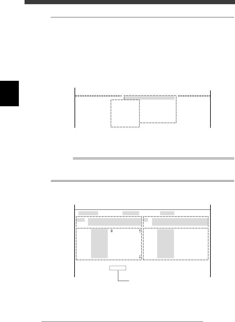
1.2 Selecting the axis
To use the joystick, you should first check or select the axis you want to
use.
1
Enter MANUAL mode.
2 Press the [SEL AXIS] or [AXIS GROUP] key on the YPU.
You can also use the <2/4/B1 SELECT SERVO MOTOR> command to
select the axis. The axis selection box appears.
Axis selection box
27301-D8-00
B1 SELECT SERVO MOTOR [AXIS]
B2 RUNNING SPEED [SPEED]
B3 POINT MOVE
B4
B5
B6 INIT.SERVO ORIGIN
B0 EXIT FROM MANUAL
<<MODE>> 4/MANUAL
<COMMAND_LIST> B/SERVO_CONTROL
A_table XY
A_table ZR
B_table X
B_table ZR
A_table Width
B_table Width
Transfer PCB
3 Select the axis.
Use the arrow keys to line up the cursor with the axis you want to move
and press the [ENTER] key.
n
NOTE
On the A1 INPUT/OUTPUT MONITOR screen, the axis can be directly switched in the
sequence each time you press the [SEL AXIS] or [AXIS GROUP] key on the YPU. The
selected axis (arm) is displayed on the lower part of the operation monitor.
Selected axis displayed on input/output monitor
27302-D8-00
HEAD
....
....
....
....
....
....
....
OUT
00000000 ....
....
....
....
....
....
....
....
IN
T2A30
.....
.....
.....
.....
.....
.....
.....
N2260
.....
.....
.....
.....
.....
.....
.....
I/O MONITOR DISP. TYPE SELECTION
Head-A HEAD 1-8 BLOW
USUAL 0 / BLOW 1
Selected Arm A_table XY
Moving Speed 20
From McahineOrigin X1= Y1= Z1= R1=
HEAD
....
....
....
....
....
....
....
OBJECT HEAD
<<MODE>> 4/MANUAL
Currently selected axis
3
-5
EPD8013110
Operation
Chapter 3
3
Manual operation
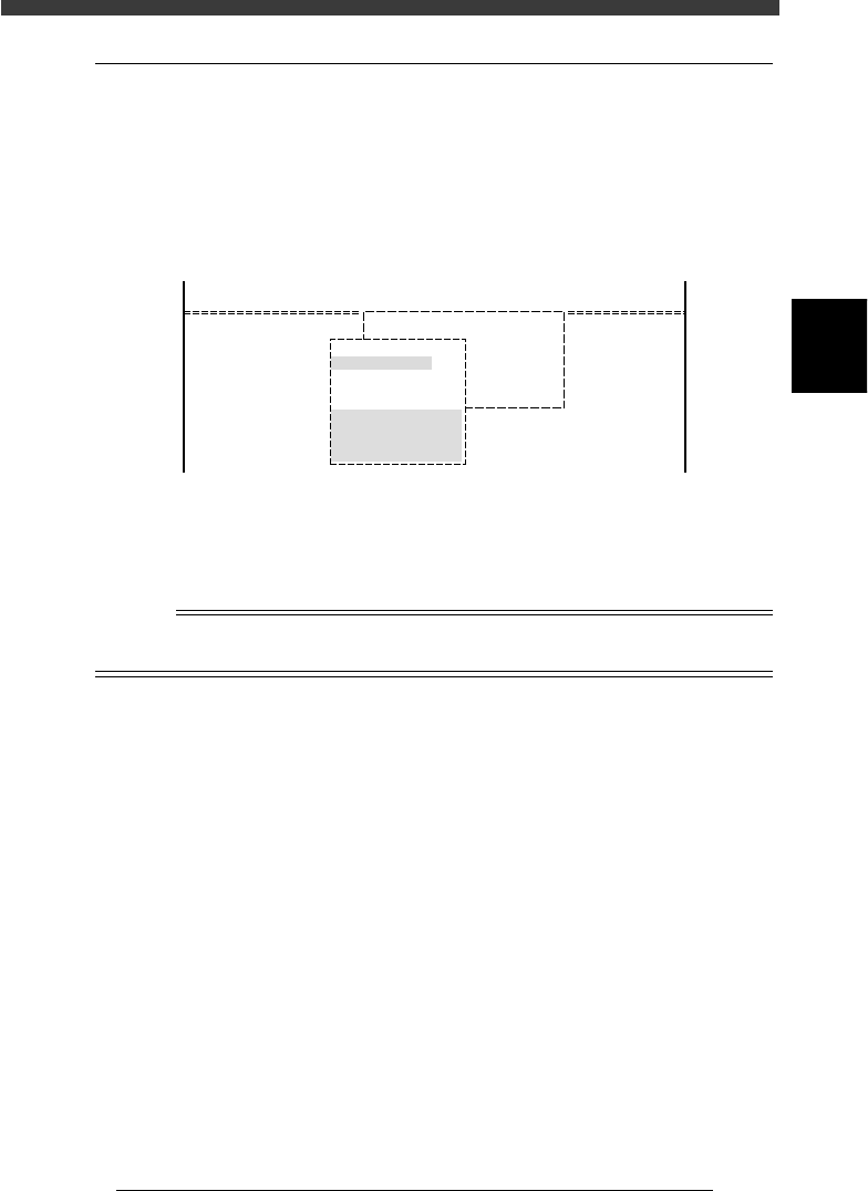
1.3 Selecting the speed
Select the speed at which you move the selected unit with the joystick.
1
Press the [SPEED] key on the YPU.
You can also use the <B2 RUNNING SPEED> command on the operation
display to select the speed.
The axis speed selection box then appears as shown below.
Axis speed selection box
27303-C0-00
<<MODE>>
<COMMAND_LIST>
4/MANUAL
B/SERVO_CONTROL
B1 SELECT SERVO MOTOR[AXIS]
B2
B3
B4
B5
B6
Edit speed.
From 1 to 100
Cursor key : Select
OK [Enter], Abort [Esc]
Speed1= 100
Speed2= 80
Speed3= 60
Speed4= 40
Speed5= 20
2
Select the speed.
Move the cursor to the desired speed setting and press the [ENTER] key.
The number “100” indicates the fastest speed.
Reference
The axis speed is set in 5 steps from “Speed 1” to “Speed 5”. These settings can be
changed with the number key.