YV180X_Ope_E.pdf - 第165页
5 -89 EPD8013110 Operation Chapter 5 5 Creating the PCB data 6. Creating the PCB infor mation This section describes how to create PCB information such as for PCB size and production methods. Flow chart for creating PCB …

5
-88
EPD8013110
Operation
Chapter 5
5
Creating the PCB data
7 Check and adjust the locate pin positions.
Check and adjust the locate pin positions so that they are aligned with the
center of the PCB positioning hole.
(This step is unnecessary when the PCB clamping method is “Edge
Clamp”.)
8 Set the push-up pins.
Set the push-up pins in proper positions on the push-up plate so that they
support the PCB from the back side when the push-up plate is raised.
(This step is unnecessary when the PCB clamping method is “Locate Pin”.)
9 Raise the locate pins.
Move the cursor to “LOCATE PIN” and press the [ENTER] key. The locate
pins rise and lower each time you press the [ENTER] key. Check that the
locate pins are securely inserted into the PCB positioning holes.
(This step is unnecessary when the PCB clamping method is “Edge
Clamp”.)
0 Cancel emergency stop and raise the push-up plate.
Move the cursor to “PUSH UP” and press the [ENTER] key. The push-up
plate rises and lowers each time you press the [ENTER] key.
(This step is unnecessary when the PCB clamping method is “Locate Pin”.)
q Quit the CONVEYOR UNITS command.
Press the [ESC] key (or select “RETURN”) to quit the CONVEYOR UNITS
command and return to the previous screen.
5
-89
EPD8013110
Operation
Chapter 5
5
Creating the PCB data
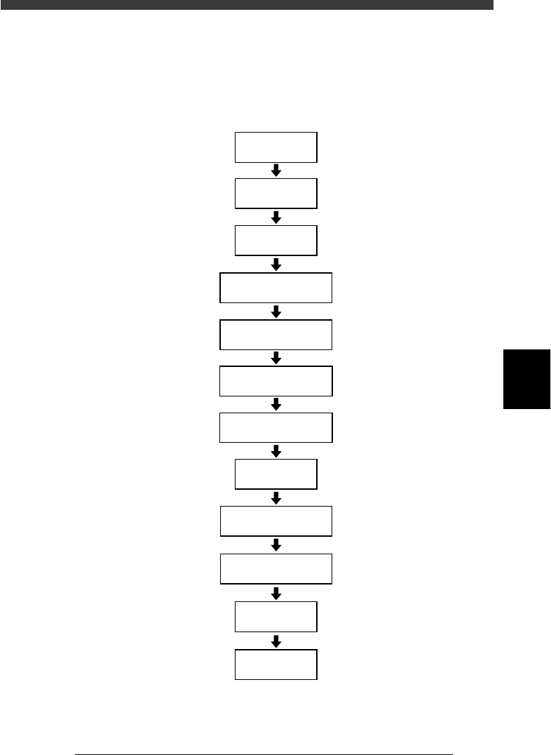
6. Creating the PCB information
This section describes how to create PCB information such as for PCB size
and production methods.
Flow chart for creating PCB information
23538-C0-00
Input
PCB Origin
Open
PCB Information
Input PCB Size
Set PCB Fiducial
Set BLOCK Fiducial
Set PCB Badmark
Set BLOCK Bad mark
Input
PCB Comment
Set
Pcb/Schedule/Block
Set
Unloader Count/Max
Set operation
conditions
Save data
5
-90
EPD8013110
Operation
Chapter 5
5
Creating the PCB data
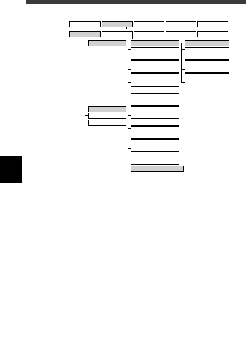
VIOS structure for “PCB Info.”
23539-C0-00
A1 MAIN WINDOW
A2 SUB WINDOW
A3 VIEW DATABASE NO.
A4
VISION ALIGNMENT DIC.
A5
A6
A7 FIND NEXT
A8
A9
A0 RETURN TO EDIT
B1 ADJUST ASSISTANT
B2 DATABASE UTILITY
B3
B4
DRAW THE SHAPE (CMP)
B5
B6 SET PALLET
B7 CONVEYOR UNITS
B8
B9
B0
TEACH, TRACE CONDITION
A/DISPLAY
B/UTILITY
C/EDIT_TOOL
D/FILE
PCB Info.
Mount Info.
Component Info.
Mark Info.
Blk Repeat Info.
Local Fidu.Info.
LocalBadMrkInfo.
1/OPERATION/M 2/DATA/M 3/MAINTE/M 4/SHELL/M 0/EXIT
1/EDIT_DATA
2/DATA_
GENERATOR
3/DATABASE 4/MANUAL 0/EXIT