YV180X_Ope_E.pdf - 第221页
5 -145 EPD8013110 Operation Chapter 5 5 Creating the PCB data 4. When you press the [T AB] once more, an asterisk (*) is prefixed to each of the two coordinate pairs, allowing you to move the entire window using the arro…
5
-144
EPD8013110
Operation
Chapter 5
5
Creating the PCB data
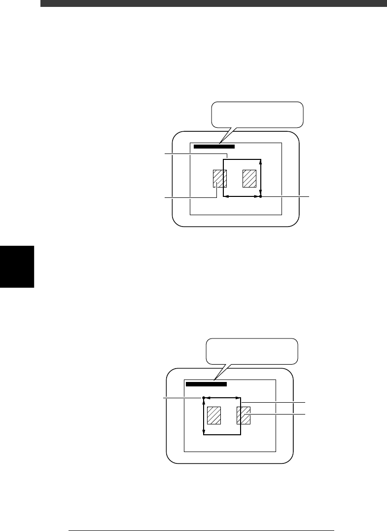
2. When you press the [TAB] key, the asterisk (*) of the right-hand
coordinates disappears as shown in the figure below. This state allows
you to enlarge or reduce the window size by changing the position of
the upper left corner with the arrow keys (the lower right corner is
stationary in this case). Adjust the window size to match the pattern or
mark size.
Adjusting the window size with the lower right corner fixed
23561-C0-00
∗(180, 170) - (338, 331)
∗(180, 170) - (338, 331)
Teaching window
Land pattern
Start (stationary)
point
3. When you want to adjust the window size by changing the position of
the lower right corner, press the [TAB] key again. The asterisk (*) of the
left-hand coordinate pair disappears but an asterisk reappears at the
right-hand coordinates, as shown in the figure below. This state allows
you to enlarge or reduce the window size by changing the position of
the lower right corner with the arrow keys (the upper left corner is
stationary in this case).
Adjusting the window size with the upper left corner fixed
23562-C0-00
(180, 170) - ∗(338, 331)
(180, 170) - ∗(338, 331)
Start (stationary)
point
Teaching windo
w
Land pattern
5
-145
EPD8013110
Operation
Chapter 5
5
Creating the PCB data
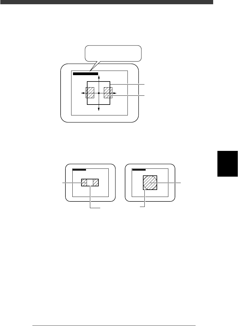
4. When you press the [TAB] once more, an asterisk (*) is prefixed to each
of the two coordinate pairs, allowing you to move the entire window
using the arrow keys.
Moving the entire window
23563-C0-00
∗(180, 170) - ∗(338, 331)
∗(180, 170) - ∗(338, 331)
Teaching windo
w
Land pattern
5. Enclose the target patterns or mark as follows.
Appropriate teaching window size
23564-C0-00
∗(180, 170) - (338, 331) ∗(180, 170) - (338, 331)
For teaching the center of patterns For teaching a mark
Pattern
Teachin
g
window
Mar
k
5
-146
EPD8013110
Operation
Chapter 5
5
Creating the PCB data
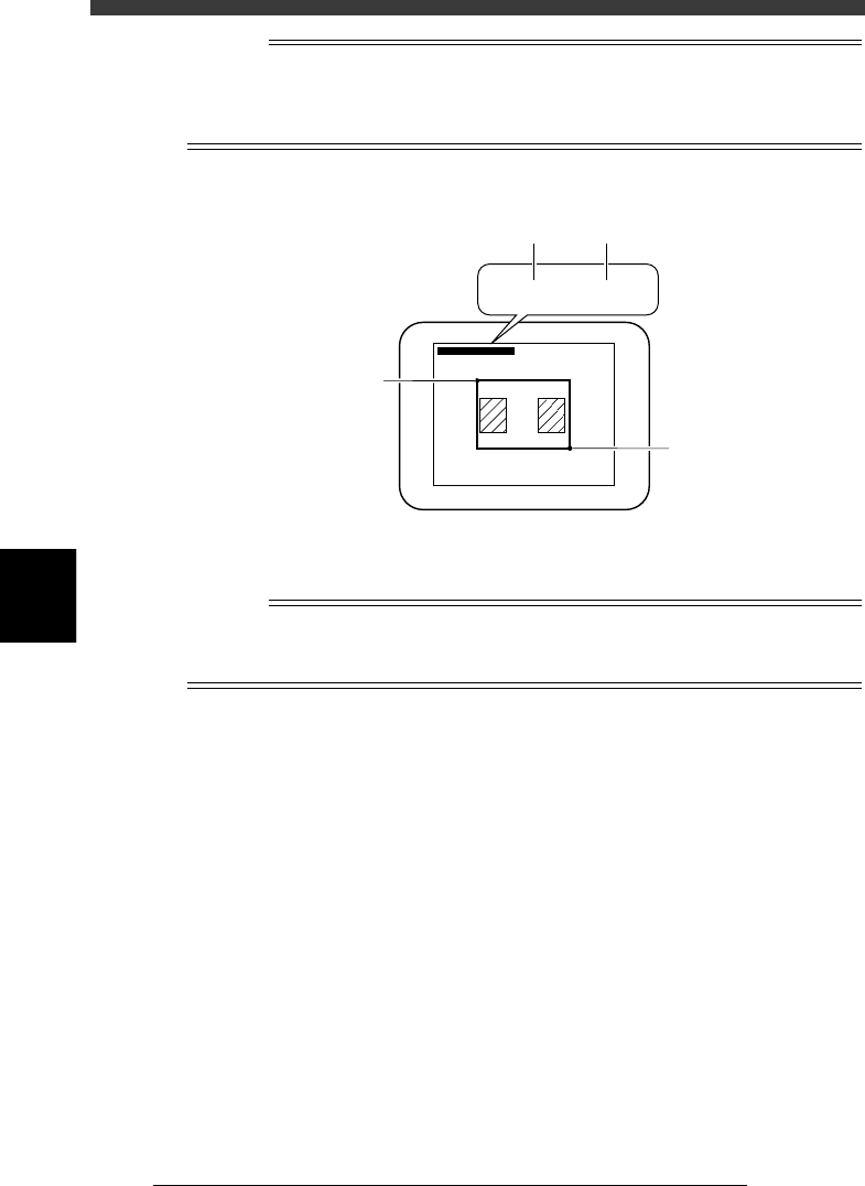
Reference
Two sets of coordinates are displayed during vision cursor teaching. The left-hand
coordinates indicate the position of the upper left corner of the teaching window, and the
right-hand coordinates indicate the position of lower right corner, both represented in
pixel units.
Teaching window position coordinates
23565-C0-00
∗(180, 170) - ∗(338, 331)
∗(180, 170) - ∗(338, 331)
B
B
A
A
5 Press the [F10] key to perform teaching.
The center coordinates of the teaching window have now been entered.
n
NOTE
Before performing vision cursor teaching, you must set teaching conditions. If you press
the [Ctrl]+[F10] keys without setting these conditions, the teaching window may not be
displayed.