YV180X_Ope_E.pdf - 第42页
4 -3 EPD8013110 Operation Chapter 4 4 Daily operation 1. Over view This chapter explains routine production flo w , including the procedures for changing PCB type and con veyor unit setups. Flow chart of routine operatio…

Chapter 4
Daily operation
1. Overview ............................................................................. 4-3
2. Inspection before operation ................................................. 4-5
3. Starting the machine ............................................................ 4-6
3.1 Turning the power ON ............................................................. 4-7
3.2 Return to origin ........................................................................ 4-9
4. Warm-up ............................................................................ 4-10
5. Starting PCB production..................................................... 4-13
6. Finishing PCB production ................................................... 4-22
7. Turning the power OFF ...................................................... 4-24
8. Changing the conveyor unit setup ...................................... 4-26
8.1 Conveyor unit setup flow ....................................................... 4-27
8.2 Conveyor width...................................................................... 4-29
8.3 Locate pins ............................................................................. 4-30
8.4 PCB support plates ................................................................. 4-31
8.5 Transfer hook.......................................................................... 4-32
8.6 Push-up pins .......................................................................... 4-33
8.7 Edge clamp (option) ............................................................... 4-34
9. HALFWAY CONTINUE command ...................................... 4-35
9.1 Loading the saved data ........................................................... 4-36
9.2 Editing mount flags ................................................................. 4-37
This chapter describes the routine operation for PCB production,
including the conveyor unit setups.
4
-3
EPD8013110
Operation
Chapter 4
4
Daily operation
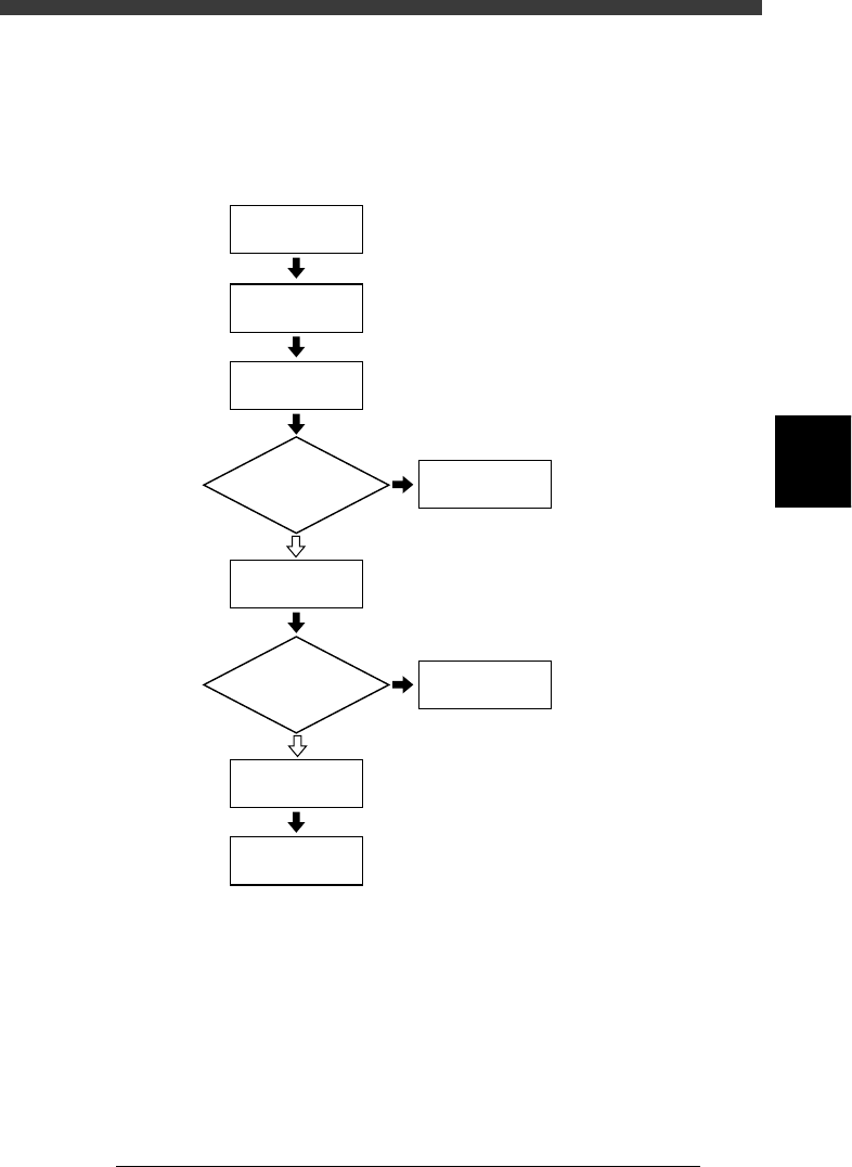
1. Overview
This chapter explains routine production flow, including the procedures for
changing PCB type and conveyor unit setups.
Flow chart of routine operation
23401-C0-00
☞
2
☞
3
☞
4
☞
5
☞
6
☞
8
☞
Chapter 5
☞
7
Start machine
Inspect before
operation
Warm up
Start
PCB production
Correct data
Change conveyor
unit setups
Finish
PCB production
Turn power off
Do you change
PCB type?
Error?
NO
YES
YES
NO
4
-4
EPD8013110
Operation
Chapter 4
4
Daily operation
4
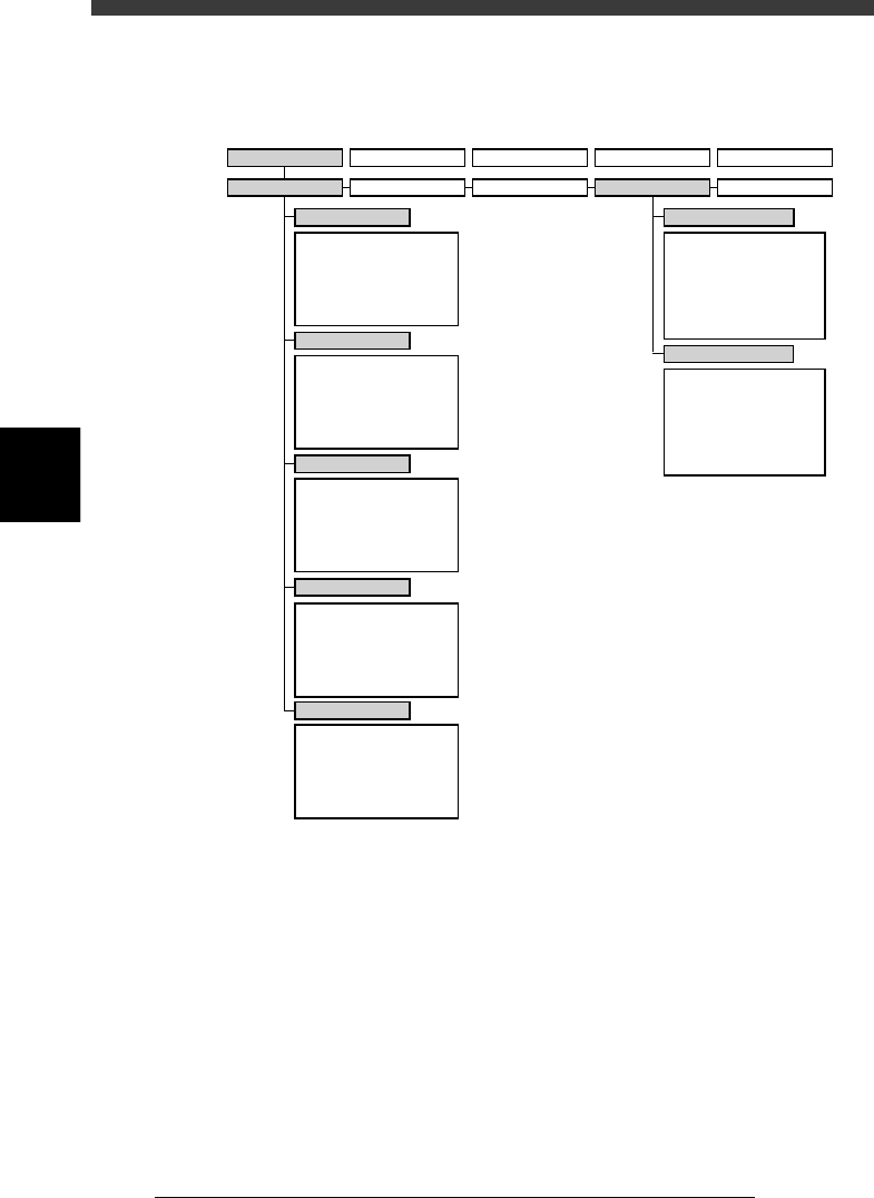
The following VIOS software modes and commands are used in this
chapter.
VIOS software modes and commands mainly used for routine operations
23402-D8-00
1/OPERATION/M 2/DATA/M 3/MAINTE/M 4/SHELL/M 0/EXIT
1/RUNNING
A/RUNNING
A1 STOP RUNNING
A2 AUTO RUNNING
A3 STEP RUNNING
A4 A_TABLE ON/OFF
A5 B_TABLE ON/OFF
A6 PCB TBL ON/OFF
B1
B2
B3
B4
B5
B6 RUNNING CONDITION
C1
AUTO RUNNING MONITOR
C2
C3
C4
C5
C6 SCROLL MONITOR
D1 WARM UP
D2 INIT.SERVO ORIGIN
D3
D4 ASSISTANT UTILITY
D5 STOPPING UTILITY
D6 RUNNING UTILITY
E1 DUMP & RESET
E2 RESET RUNNING
E3
E4 HALFWAY CONTINUE
E5 CYCLE STOP
E0 EXIT FROM RUNNING
B/CONDITION
C/MONITOR
D/INITIALIZE
E/SKIP&EXIT
A/IO UTILITY
A1
INPUT/OUTPUT MONITOR
A2
FEEDER OUT MONITOR
A3
A4 VACUUM IN MONITOR
A5 CHANGE NOZZLE
A6 ATS/YTF PALLET
A0 CONVEYOR UNITS
B1
SELECT SERVO MOTOR
B2 RUNNING SPEED
B3 POINT MOVE
B4
B5
B6 INIT.SERVO ORIGIN
B0 EXIT FROM MANUAL
B/SERVO_CONTROL
2/PRD.DATA 3/PRD.HISTORY 4/MANUAL 0/EXIT