YV180X_Ope_E.pdf - 第128页
5 -52 EPD8008100 Operation Chapter 5 5 Creating the PCB data 7 Register the edited data. When you have edited the ball lead information, press the [ENTER] key to register the edited data in the BGA ball data registration…
5
-51
EPD8008100
Operation
Chapter 5
5
Creating the PCB data
Utility messages for editing the BGA ball lead information
27518-C0-00
V400
[BGA BALL DATA UTILITY]
Please select command.
(1) [Enter] key :[EDIT & REGISTRATION]
(2) [Tab] key :[DELETE DATA]
(3)any other key :[EXIT]
V401
There is no data for this component.
Do you make new data and edit it?
Please select.
[Enter] key :EXEC
any other key :CANCEL
V413
[BGA ball data edit] will e executed
on vision monitor.
To start to edit, please press any key.
V404
How to edit [BGA ball data]
[Arrow] key :move cursor
[Space] key :one ball ON/OFF
[F1] key :horizontal line all ON
[F2] key :vertical line all ON
[F3] key :horizontal line all OFF
[F4] key :vertical line all OFF
[Enter] key :exit
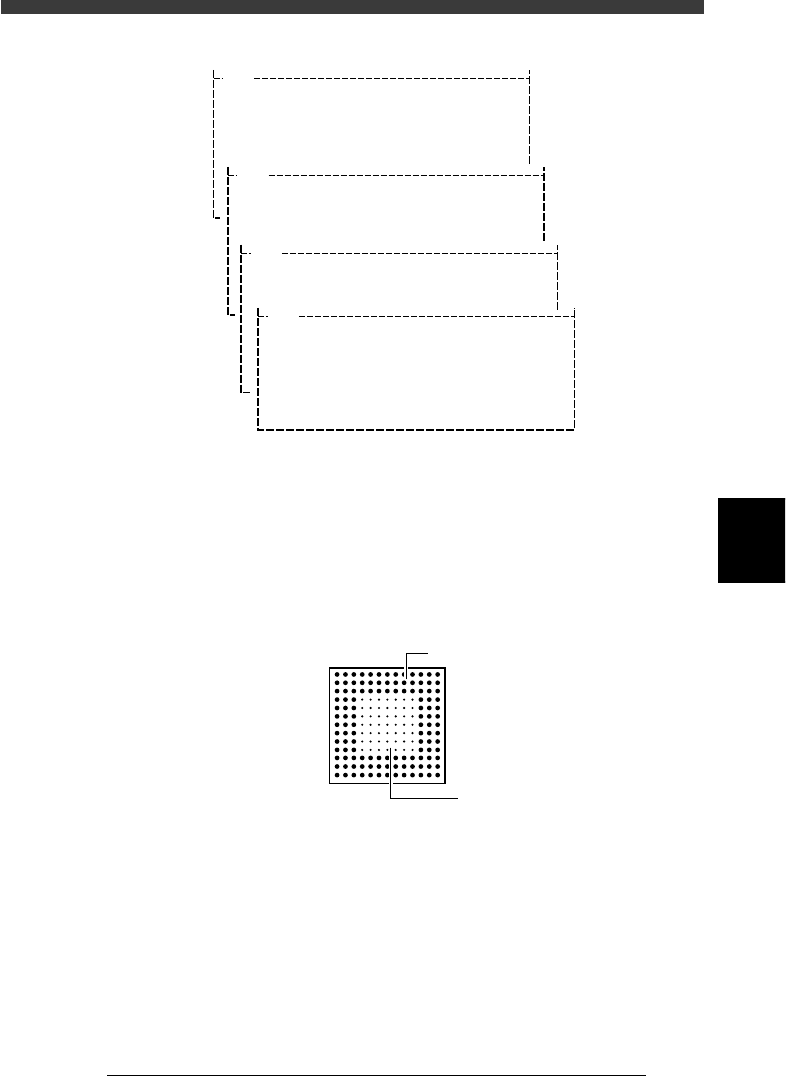
6 Edit the ball lead position data.
When the BGA ball lead information edit screen appears on the upper left
of the vision monitor, edit it while referring to the utility messages
displayed on the operation monitor, so that the ball lead display on the
edit screen exactly matches the ball lead arrangement of the actual
component. The ball lead display should be set to ON at positions where
the ball lead exists and to OFF where it does not exist.
BGA ball lead information edit screen
21501-C0-00
Hn:13
Vn:13
N: 0
nh:1
nv:1
ON
OF
F
5
-52
EPD8008100
Operation
Chapter 5
5
Creating the PCB data
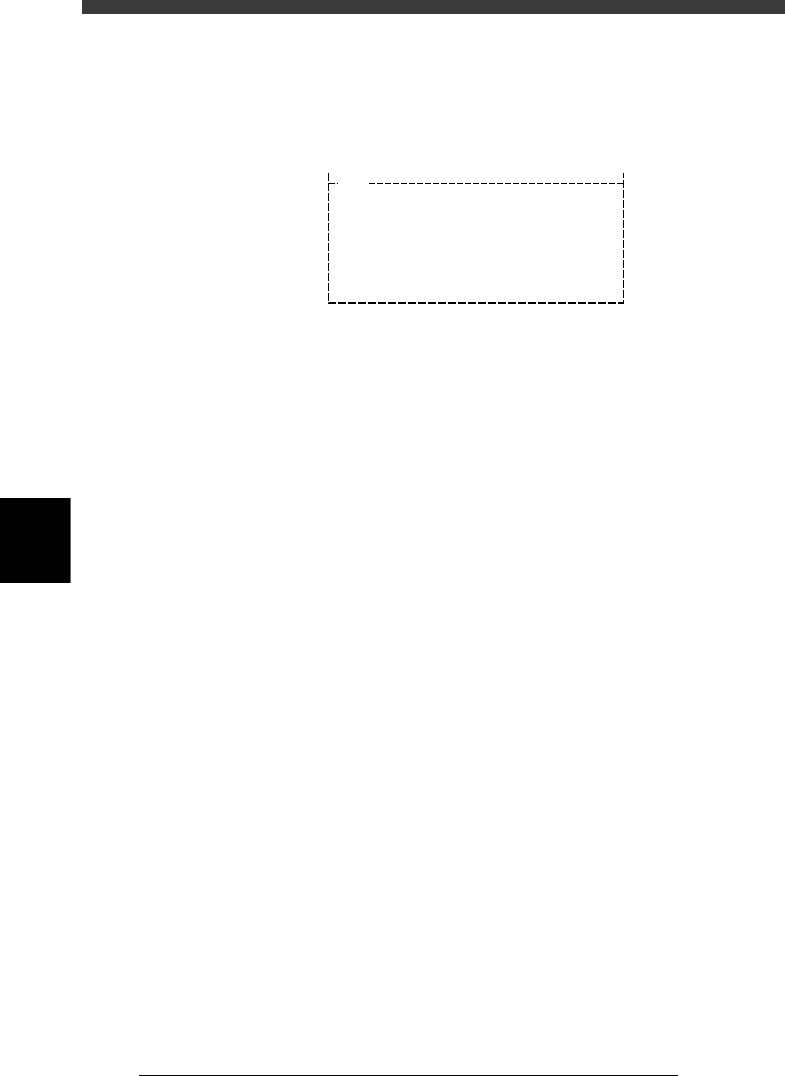
7 Register the edited data.
When you have edited the ball lead information, press the [ENTER] key to
register the edited data in the BGA ball data registration boxes. Follow the
messages displayed on the operation monitor to complete the registration.
BGA ball data registration boxes
27519-C0-00
V400
[BGA BALL DATA UTILITY]
Please select command.
(1) [Enter] key :[EDIT & REGISTRATION]
(2) [Tab] key :[DELETE DATA]
(3) any other key :[EXIT]
8 Execute the VISION TEST commands again.
Repeat the VISION TEST command a few times. If no error occurs, the
BGA ball lead data is appropriate. Execute the PICK UP COMP command
to remove the component from the nozzle, the DISCARD COMP com-
mand to turn off the vacuum generation, and the EXIT command to quit
the Adjust Assistant mode.
If an error occurs, proceed to the next section “Adjusting the Binary
Level”.
5
-53
EPD8008100
Operation
Chapter 5
5
Creating the PCB data
●Adjusting the Binary Level
If the mold part of the BGA package reflects light during recognition of the
ball leads, the reflected light may be misdetected as a lead, resulting in a
ball lead recognition error. To avoid this type of error, increasing the ball
lead area will prove effective.
1 Set the Monitor Mode parameters to “FINE LINE”.
Press the right arrow key to move the cursor to the Adjust Assistant Items
window, then set the Monitor Mode parameter to “FINE LINE”.
2 Execute the VISION TEST command.
Press the left arrow key to move the cursor back to the command window,
then execute “VISION TEST”.
If the mold part of the BGA is displayed in white on the vision monitor,
you will need to adjust the binary level as described below.
3 Press the [TAB] key to move the cursor into the sub-
window of the component information.
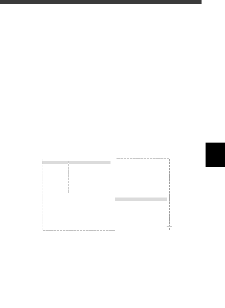
4 Adjust the Binary Level value in the SHAPE INFO.
subwindow.
Enter a value which is estimated from the percentage of the mold part area
displayed in white versus the entire area of the ball leads.
Binary Level adjustment
27520-C0-00
6. SHAPE INFO.
Binary Level
:
:
:
:
:
:
:
:20
Comp. Name : BGA
Adjust Assistant Items
Monitor Mode Find Line
Command
VISION TEST
Binary level settin
g
5 Repeat the VISION TEST command.
When no error occurs, the binary level is correct.
6 Save the settings.
Exit the Adjust Assistant mode, then press the [ESC] key twice, select <2/1/
D8 SAVE PCB DATA> and press the [ENTER] key.