YV180X_Ope_E.pdf - 第120页
5 -44 EPD8008100 Operation Chapter 5 5 Creating the PCB data 27. Pick V acuum, Mount V acuum These are reference vacuum pressures used for checking the pickup and mount vacuum levels. Use the default settings and adjust …

5
-43
EPD8008100
Operation
Chapter 5
5
Creating the PCB data
1. BASIC INFO. parameters
1. Comp. Package
Refer to the description in “3.3.1 Standard chip components”.
2. Feeder Type
Refer to the description in “3.3.1 Standard chip components”.
3. Required Nozzle
Select the optimum nozzle that matches the component size from among
the nozzle types for QFP components. (See “Nozzle table” listed in
Supplement in this manual.)
4. Feeder Set No.
Refer to the description in “3.3.1 Standard chip components”.
5. Pos. Definition
Refer to the description in “3.3.1 Standard chip components”.
6. Feeder Pos_X
Refer to the description in “3.3.1 Standard chip components”.
2. OPTION INFO. parameters
For descriptions of the following OPTION INFO. parameters, refer to
“3.3.1 Standard chip components” in this chapter.
11. FixCmpRef.
12. Alt. Comp.
13. Use feeder opt.
14. Comp. Group No.
15. Correct Pickpos.
3. PICK & MOUNT INFO. parameters
21. Pick Angle deg
Use the same setting as for QFP components.
22. Pick Timer, Mount Timer
Refer to the description in “3.4.2 SOP component”.
23. Pick Height, Mount Height
Refer to the description in “3.3.1 Standard chip component”.
24. Pick Sequence
Refer to the description in “3.3.1 Standard chip component”.
25. Mount Action
Set this parameter to “QFP” when mounting accuracy is more important
than operation speed. (Refer to the description in “3.3.4 QFP components”
for detail.)
26. Vacuum Check
Set this parameter to “SPECIAL CHK” in most cases. (Refer to the
description in “3.3.4 QFP components” for detail. )

5
-44
EPD8008100
Operation
Chapter 5
5
Creating the PCB data
27. Pick Vacuum, Mount Vacuum
These are reference vacuum pressures used for checking the pickup and
mount vacuum levels. Use the default settings and adjust them as needed
in the Adjust Assistant mode. (See “3.7” in this chapter.)
28. Conv. Y Speed
Refer to the description in “3.3.1 Standard chip components”.
4. DUMP INFO. parameters
31. Dump Way
Set to “Station” when a dump station (option) is used and to “Dump POS.”
when not used. Refer to the Discard point parameter explained in the
mounter service manual.
32. Retry Times
Refer to the description in “3.3.1 Standard chip components”.
5. VISION INFO. parameters
41. Alignment Group
Set to “Ball”.
42. Alignment Type
Use the default setting “Simple BGA”.
43. AlignmentModule
This parameter specifies the lighting method for recognizing a component.
Use the default setting (Fore).
44. Light Selection
Set to “Main+Coax” when editing the ball lead arrangement. When you
want to check nicked ball leads, set this parameter to “Only Side”.
For descriptions of the following VISION INFO. parameters, refer to
“3.3.1 Standard chip components”.
45. Lighting Level
46. Comp. Threshold
This parameter is skipped for BGA components.
47. Comp. Tolerance
48. Search Area
49. Datum Angle
50. Comp. Intensity
51. MultiCam. Marker
5
-45
EPD8008100
Operation
Chapter 5
5
Creating the PCB data
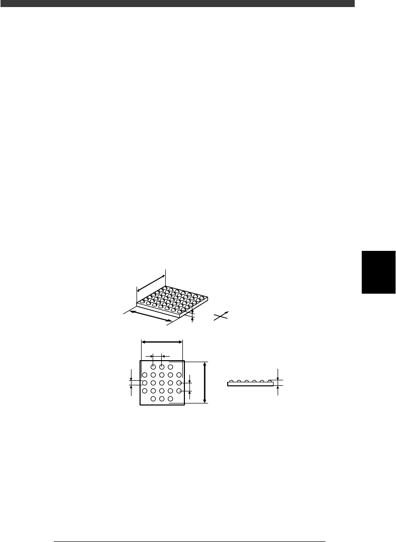
6. SHAPE INFO. parameters
When “Alignment Type” in the VISION INFO. sub-window is set to
“Simple BGA”, the following parameters are displayed in the SHAPE
INFO. sub-window.
61. Body Size X, Body Size Y
Enter the correct dimensions measured with a vernier caliper or microme-
ter.
62. Body Size Z
Enter the correct diameter measured with a vernier caliper or micrometer.
63. Dot number N, Dot number E
Enter the number of ball terminals arrayed in the N and E directions. If the
number of terminals per array differs from each other, enter the largest
number of terminals per array.
64. BGA diameter
Enter the diameter of ball terminals.
65. BGA pitch
Enter the spacing between ball terminals.
66. Dot amount
Enter the total number of ball terminals of the BGA component.
SHAPE INFO. parameters for BGA component
23515-C0-00
N
S
E
W
B
A
C
D
E
F
H
G
C
A : Body Size X
B : Body Size Y
C : Body Size Z
D : Dot number N
E : Dot number E
F : BGA pitch N
G : BGA pitch E
H : BGA diamete
r
Side view
Bottom view