YV180X_Ope_E.pdf - 第56页
4 -17 EPD8013110 Operation Chapter 4 4 Daily operation 6 Display the information monitor as necessary . If you want to display the information monitor during operation, press the [F4]. Each time you press the [F4] key , …
4
-16
EPD8013110
Operation
Chapter 4
4
Daily operation
4
4
Select the operation speed.
The currently selected speed is displayed in the CONDITION monitor at
the left of the screen. If you want to change this speed, proceed as follows.
1. Press the [SPEED] key on the YPU (or execute “RUNNING SPEED” in
<1/1/ D6 RUNNING UTILITY>).
The 5-step speed selection box then appears.
2. Line up the cursor with the desired speed and press the [ENTER] key.
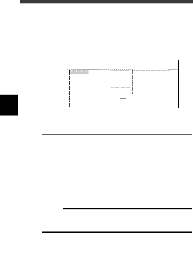
CONDITION monitor and RUNNING SPEED command
27406-C0-00
Condition
Speed 100
<<<APPLICATION>>> 1/OPERATION/M
<<MODE>> 1/RUNNING
<<COMMAND_LIST>>
RUNNING UTILITY
RUNNING SPEED [SPEED]
Speed = 100
Speed = 80
Speed = 60
Speed = 40
Speed = 20
D/INITILIZE
Displays current running speed
Select desired speed
Reference
The operation speed is preset in 5 steps from Speed 1 to Speed 5. If you want to change
these settings, use the <B2 RUNNING SPEED> command in MANUAL mode.
5
Start operation.
1. Release the emergency stop button and press the [READY] key.
2. Check the surrounding area for safety, then press the [RUN] key on the
YPU (twice) or operation panel, or execute the <1/1/A2 AUTO
RUNNING> command.
3. If the alert message for changing the conveyor width appears, check
safety again and press the [ENTER] key or [RUN] key.
The W-axis moves to set the proper PCB width and the machine is now
ready to receive a PCB.
4. When the entrance sensor detects a PCB, the conveyor motor begins to
rotate to carry the PCB to the mounting position and the machine starts
mounting components.
w
WARNING
A DANGEROUS SITUATION CAN OCCUR IF ANY PART OF THE BODY
ENTERS THE MOVEMENT RANGE OF THE HEAD ASSEMBLY DURING
OPERATION (GREEN WARNING LAMP IS LIT). BE SURE TO STAY OUT OF
THE MOVEMENT RANGE DURING OPERATION.
4
-17
EPD8013110
Operation
Chapter 4
4
Daily operation
6
Display the information monitor as necessary.
If you want to display the information monitor during operation, press the
[F4]. Each time you press the [F4] key, the information monitor changes in
the order of “SEQUENCE MONITOR”, “I/O MONITOR”, “PRODUCTION
MONITOR”, “VISION MONITOR”, “RETRY MONITOR”, “BIGNUM
MONITOR“, “CONV. MONITOR” and “ CO-PLANARITY MONITOR”. To
close the information box, press the [F4] key once more.
Reference
Information monitors can be displayed by executing the <1/1/C1 /AUTO RUNNING
MONITOR> command.
1. SEQUENCE MONITOR
The SEQUENCE MONITOR shows the progress of component pickup,
recognition and mounting. For the meaning of each code displayed in the
box, place the cursor on the <1/1/C1 AUTO RUNNING MONITOR> -
”MONITOR SEQUENCE” and press the [F1] key to see the help message.
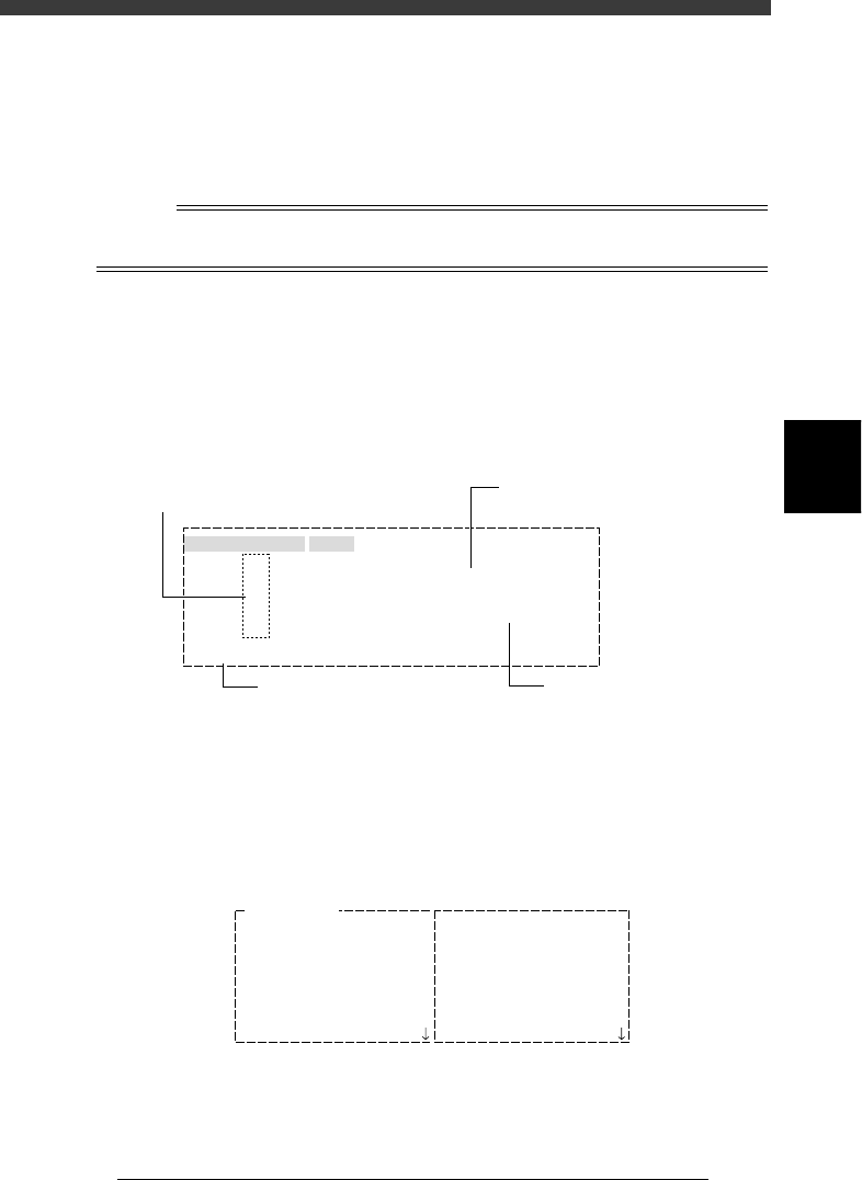
SEQUENCE MONITOR window
27407-D8-00
Mounted the Component
BLK
BLK
#11
#61
#21
#71
#31
#81
#41
#91
#51
#101
1
1
MMMMMMMMMMMMMMMMMMMMMMMMMMMMMMMMM
MMMMMvvv
#1
#51
A table
SEQUENCE MONITOR
Atable
Btable
Atable
Btable
Mount data No.
Block No. in which components
are being mounted
Mounting status is shown
by code
Mounting status description
P: Picking up
V: Processing image
M: Mounting
D: Discarding
2. I/O MONITOR
The I/O MONITOR allows you to monitor the digital I/O signals changing
with the mounting operation. To see the next or previous screen, press the
[PageUp] or [PageDown] key ([Fn]+[
↑
] or [Fn]+[
↓
] keys).
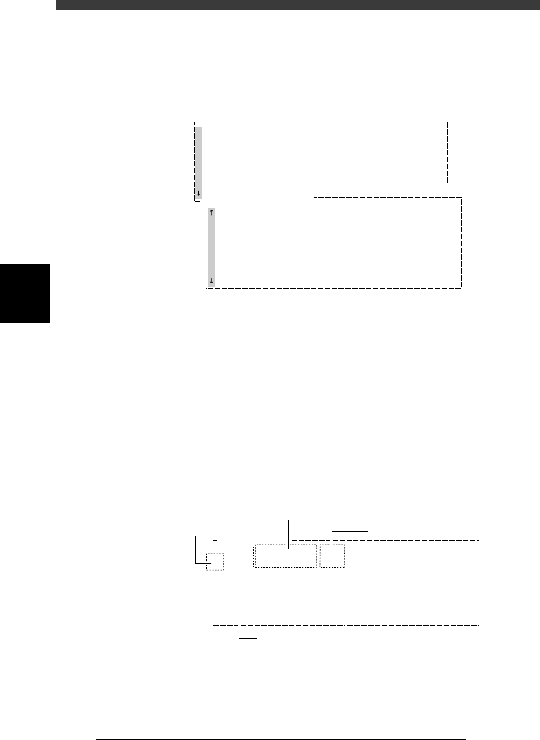
I/O MONITOR window
27408-D8-00
IO MONITOR
T2A00
T2B00
T2A10
T2B10
T2A37
T2B67
T2A65
T2B35
HEAD
HEAD
HEAD
HEAD
HEAD
HEAD
HEAD
HEAD
00000000
00000000
00000000
00000000
0
0
0
0
N2260
N2360
N2270
N2370
N230
N2330
N2223
N2323
HEAD
HEAD
HEAD
HEAD
HEAD
LIGHT
LIGHT
HEAD
00000000
00000000
00000000
00000000
00000000
00000000
0
0
4
-18
EPD8013110
Operation
Chapter 4
4
Daily operation
4
3. PRODUCTION MONITOR
The PRODUCTION MONITOR shows information on PCB production in
progress. To see the next or previous screen, press the [PageUp] or
[PageDown] key ([Fn]+[
↑
] or [Fn]+[
↓
] keys).
PRODUCTION MONITOR window
27409-C0-00
PRODUCTION MONITOR
PCB/SCHEDULE/BLOCK
UNLOADER COUNT/MAX
TOTAL TACT(sec/pcb)
SET PCB(sec/pcb)
WAITING(sec/pcb)
0
0
0
0
0
PRODUCTION MONITOR
Component Name SetNo.
F20
F21
F23
F24
F25
F26
F27
F28
Count
12
20
10
40
12
10
0
1
Error
0
0
0
0
0
0
0
0
Pallet Counter/Total
1
2
3
4
5
6
7
8
4. VISION MONITOR
The VISION MONITOR informs you of the component recognition status
of the vision system. The contents displayed in this window depend on the
password level.
• Password Level D:
The monitor shows the XYR offset values for each head which are detected
to correct the position of a component picked up and also shows error
code if an error occurred. Error numbers are indicated in the CEME
column. For the meaning of each number displayed in the box, place the
cursor on the <1/1/C1 AUTO RUNNING MONITOR> - ”MONITOR
VISION” and press the [F1] key to see the help message.
VISION MONITOR window (1)
27410-C0-00
Comp
7
X
-0.03
Y
-0.10
R
-0.05
CEME
0
1
Comp
21
X
-0.30
Y
0.02
R
0.12
CEME
1-22
VISION MONITOR
Offset detected by vision system
Head No.
Error code
Component No.