YV180X_Ope_E.pdf - 第211页
5 -135 EPD8013110 Operation Chapter 5 5 Creating the PCB data 1 Open the corresponding screen. In the <1/2/PRD.DA T A> mode, open the PCB Info. screen to correct the PCB origin, and open the Blk Repeat Info. screen…
5
-134
EPD8013110
Operation
Chapter 5
5
Creating the PCB data
4 Perform teaching to correct the mounting position.
1. Manipulate the YPU joystick so that the cross cursor is aligned with the
center of the land patterns.
2. Press the [F10] key twice to enter the correct coordinates of the center
of the land patterns.
2. Particular component shift from the mounting positions
When a particular component shifts from its mounting position, the
component may not be recognized correctly. Open the Component Info.
screen in the <1/2/PRD.DATA> mode and run the Adjust Assistant for
the data you want to check.
Refer to “3. Creating the component information” for details on the
Adjust Assistant.
3. Mounting position shift on the entire PCB or in a particular
block
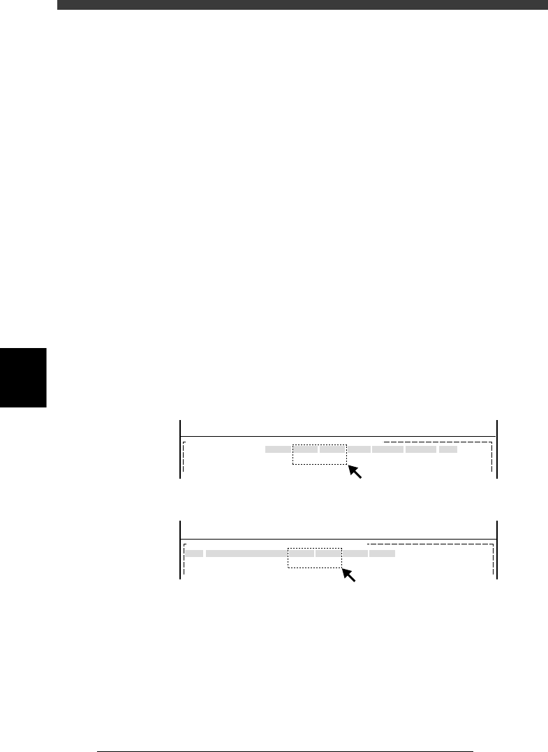
When the mounting position for the entire PCB shifts, the “PCB Origin”
settings in the PCB Info. are probably incorrect (A in the figure below).
When the mounting position for a particular block shifts, the coordinate
settings in the Blk Repeat Info. are probably incorrect (B in the figure
below).
Correcting mounting position errors
27560-C0-00
MARK
X/X1
10.00
Y/Y1
10.00
MRK2 X2
Y2 Skip?
<<<APPLICATION>>> 2/DATA/M
<<MODE>> 1/EDIT_DATA
OBJ :PCB Info.PCB :
PCB Origin
No.
1
2
X
0.00
Y
0.00
Block Comment Skip?
Exec
R
0.00
<<<APPLICATION>>> 2/DATA/M
<<MODE>> 1/EDIT_DATA
OBJ : Blk Repeat Info.PCB :
A: When mounting position shift occurs on the entire PCB :
B: When mounting position shift occurs in particular block:
A
B
5
-135
EPD8013110
Operation
Chapter 5
5
Creating the PCB data
1 Open the corresponding screen.
In the <1/2/PRD.DATA> mode, open the PCB Info. screen to correct the
PCB origin, and open the Blk Repeat Info. screen to correct the block
repeat settings.
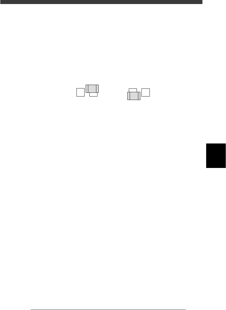
2 Enter the mounting error.
If the position shifts in the plus direction (A in the figure below), subtract
the error from the current coordinate value, and add the error if the
position shifts in the minus direction (B in the figure below).
Mounting position error
21504-C0-00
AB
3 Save the data.
When you have corrected the data, select <1/2/C0 SAVE & EXECUTE> and
press the [ENTER] key. The corrected data will be saved.
4. Mounting position errors even when fiducial marks are used
When the mounting position of the entire PCB or a particular block has
shifted even if the PCB corrections have been made by using the
fiducial marks, an extraneous mark may be recognized due to incorrect
settings for the fiducial mark coordinates. Open the Mark Info. screen in
the <1/2/PRD.DATA> mode, and perform the Adjust Assistant to adjust
the data you want to check. Refer to “4. Creating the mark information”
in this chapter for details on the Adjust Assistant.
5
-136
EPD8013110
Operation
Chapter 5
5
Creating the PCB data
11. Data backup
Making a backup copy of data is recommended for cases in which the
registered PCB data is corrupted or lost. To make a backup copy of PCB
data, you need a PCB data disk specially formatted for the YAMAHA
mounters. This section explains how to format a PCB data disk and make a
backup.
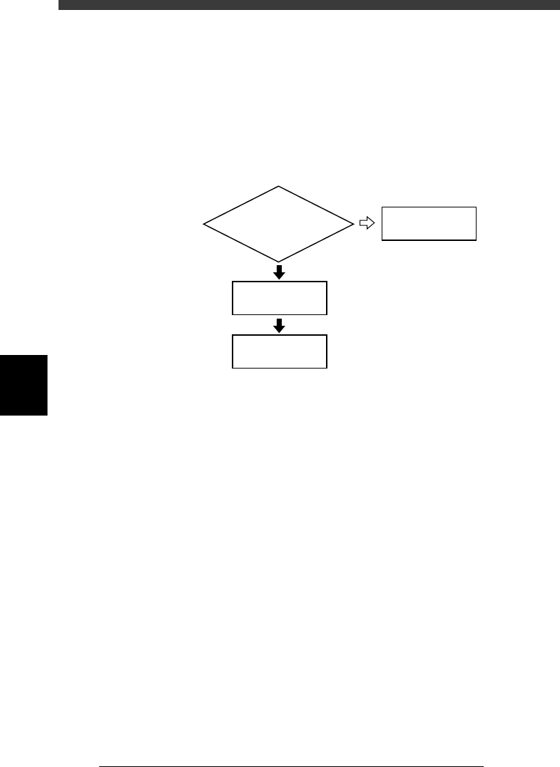
Data backup flow
23559-C0-00
Insert floppy disk
into machine
Do you have PCB disk
for backup ?
4/1/D1/MAKE
PCB DATA DISK
Back up data
11.1
☞
11.2
☞
NO
YES