YV180X_Ope_E.pdf - 第111页
5 -35 EPD8008100 Operation Chapter 5 5 Creating the PCB data 23. Pick Height, Mount Height Refer to the description in “ 3.3.1 Standard chip components ” . 24. Pick Sequence Refer to the description in “ 3.3.1 Standard c…
5
-34
EPD8008100
Operation
Chapter 5
5
Creating the PCB data
3. PICK & MOUNT INFO. parameters
21. Pick Angle deg
This parameter specifies the angle through which the mounter head rotates
to pick up a component on the feeder. This setting determines the orienta-
tion of the component (recognition reference) when it is recognized and
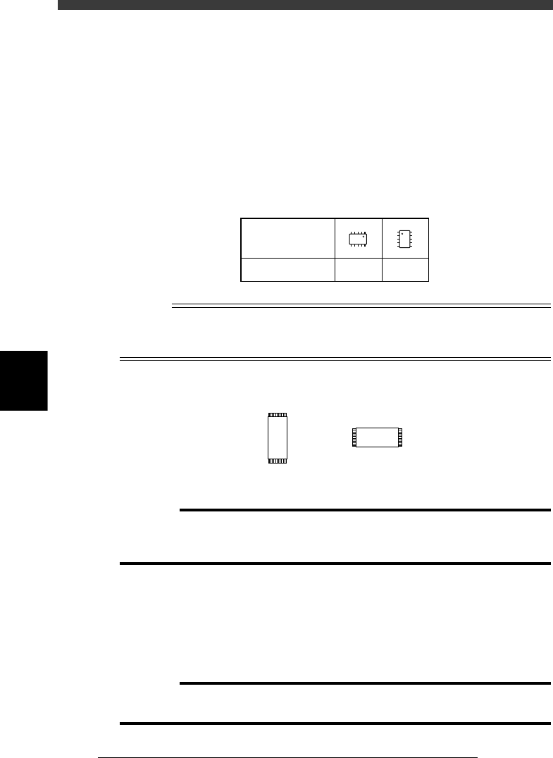
displayed on the vision monitor. The pickup angle for SOP components
must be specified so that their leads face the EW directions. Set this
parameter to 0° for horizontally long components in the loading position,
and set to 90° for vertically long components. Select the correct pickup
angle referring to the table below.
SOP component pickup angle
25507-C0-00
0 deg. 90 deg.
Loading position
Pickup angle
NS
E
W
N
S
WE
n
NOTE
For components having leads on the short sides like TSOP, set the Pick Angle deg
parameter to 0° when the loading position is vertically long, and to 90° when horizontally
long.
TSOP
23512-C0-00
0˚ 90˚
c
CAUTION
Pickup angle setting directly affects the recognition reference and mounting angle. Be
careful not to mistake 0° for 180° for horizontally long components in the loading
position and 90° for -90° for vertically long components.
22. Pick Timer, Mount Timer
These parameters specify the time duration (in seconds) for which the head
stays in the lowered position after detecting the reference pickup or mount
vacuum pressure when picking up or mounting a component. In most
cases, it is okay to set these parameters to “0.00”. If pickup or mount
operation is not stable, set a longer timer value.
c
CAUTION
Setting the Pick Timer and Mount Timer longer than necessary may have adverse
effects on the cycle time.

5
-35
EPD8008100
Operation
Chapter 5
5
Creating the PCB data
23. Pick Height, Mount Height
Refer to the description in “3.3.1 Standard chip components”.
24. Pick Sequence
Refer to the description in “3.3.1 Standard chip components”.
25. Mount Action
This specifies the nozzle descent movements during component mounting.
Set this parameter to “Normal” in most cases.
26. Vacuum Check
Refer to the description in “3.3.1 Standard chip components”.
27. Pick Vacuum, Mount Vacuum
These are reference vacuum pressures used for checking the pickup and
mount vacuum levels. Use the default settings and adjust them as needed
in the Adjust Assistant mode. (See “3.7” in this chapter.)
28. Conv. Y Speed
Refer to the description in “3.3.1 Standard chip components”.
4. DUMP INFO. parameters
31. Dump Way
Set to “Dump POS” (discard point). See the mounter service manual for
details on the discard point.
32. Retry Times
Refer to the description in “3.3.1 Standard chip components”.
5. VISION INFO. parameters
41. Alignment Group
Set this parameter to “IC”.
42. Alignment Type
Set this parameter to “SOP”.
43. AlignmentModule
This parameter specifies the lighting method for recognizing a component.
Use the default setting (Fore&Back&Laser) in most cases. Refer to the
description in “3.3.1” for more details.
For descriptions of the following VISION INFO. parameters, refer to
“3.3.1 Standard chip components”.
44. Light Selection
45. Lighting Level
46. Comp. Threshold
47. Comp. Tolerance
48. Search Area
49. Datum Angle
50. Comp. Intensity
51. MultiCam. Marker
5
-36
EPD8008100
Operation
Chapter 5
5
Creating the PCB data
6. SHAPE INFO. parameters
Set these parameters after specifying the VISION INFO. parameters. If
“Alignment Type” is undefined, the following parameters are not dis-
played.
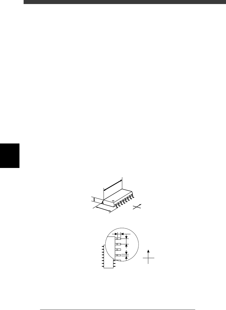
61. Body Size X, Body Size Y
Enter the correct dimensions including the leads, measured with a vernier
caliper or micrometer.
62. Body Size Z
Enter the correct thickness measured with a vernier caliper or micrometer.
63. Ruler Offset
Refer to the description in “3.4.1 Mini-mold transistors/SOT”.
64. Ruler Width
Refer to the description in “3.4.1 Mini-mold transistors/SOT”.
65. LeadNumber
Enter the number of leads existing on one side in either E or W direction
66. ReflectLL
Enter the projected length of leads which reflect light during recognition.
Use the default setting in most cases.
67. LeadWidth
Enter the correct lead width.
68. LeadPitch
Enter the correct lead pitch (lead-to-lead spacing).
SHAPE INFO. parameters for SOP components
23513-C0-00
N
S
E
W
B
C
A
A : Body Size X
B : Body Size Y
C : Body Size Z
D : Reflect LL
E : LeadPitch
F : LeadWidth
Bottom view
N
S
W
E
D
E
F