YV180X_Ope_E.pdf - 第133页
5 -57 EPD8008100 Operation Chapter 5 5 Creating the PCB data 50. Comp. Intensity 51. MultiCam Marker 6. SHAPE INFO. parameters Set these parameters after specifying the VISION INFO. parameters. If “ Alignment T ype ” is …

5
-56
EPD8008100
Operation
Chapter 5
5
Creating the PCB data
Connector pickup angle
25509-C0-00
0 deg. 180 deg. 90 deg. -90 deg.
Loading
position
Recognition
reference
Pickup angle
22. Pick Timer, Mount Timer
Refer to “3.4.2 SOP components” in this chapter.
For descriptions of the following PICK & MOUNT INFO. parameters,
refer to “3.3.1 Standard chip components” in this chapter.
23. Pick Height, Mount Height
24 Pick Sequence
25. Mount Action
26. Vacuum Check
27. Pick Vacuum, Mount Vacuum
28. Conv. Y Speed
4. DUMP INFO. parameters
31. Dump Way
Set to “Dump POS”. Refer to the Discard point parameter explained in the
mounter service manual.
32. Retry Times
See the description of “3.3.1 Standard chip components”.
5. VISION INFO. parameters
41. Alignment Group
Set to “Connector”.
42. Alignment Type
Set to “Con-E”.
For descriptions of the following VISION INFO. parameters, refer to
“3.3.1 Standard chip components”.
43. AlignmentModule
44. Light Selection
45. Lighting Level
46. Comp. Threshold
47. Comp. Tolerance
48. Search Area
49. Datum Angle
5
-57
EPD8008100
Operation
Chapter 5
5
Creating the PCB data
50. Comp. Intensity
51. MultiCam Marker
6. SHAPE INFO. parameters
Set these parameters after specifying the VISION INFO. parameters. If
“Alignment Type” is undefined, the following parameters are not dis-
played.
61. Body Size X, Body Size Y
Enter the correct dimensions including the leads, measured with a vernier
caliper or micrometer.
62. Body Size Z
Enter the correct thickness measured with a vernier caliper or micrometer.
63. Ruler Offset
Refer to the description in “3.4.1 Mini-mold transistors/SOT”.
62. Ruler Width
Refer to the description in “3.4.1 Mini-mold transistors/SOT”.
63. LeadNumber
Enter the number of leads existing on one side in either E or W direction.
64. ReflectLL
Enter the projected length of leads which reflect light during recognition.
Use the default setting in most cases.
65. LeadWidth
Enter the correct lead width.
66. LeadPitch
Enter the correct lead pitch (lead-to-lead spacing).
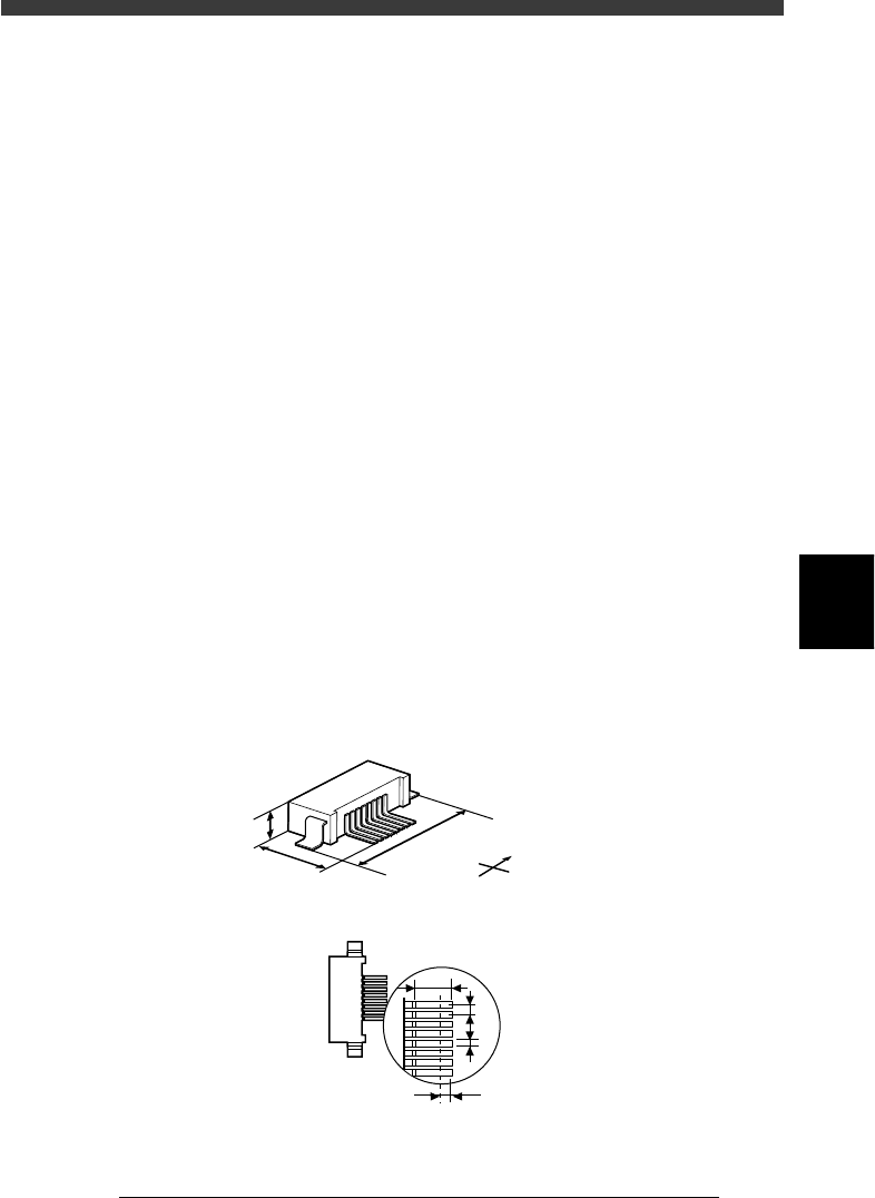
SHAPE INFO. parameters for connectors
23517-C0-00
S
N
W
E
B
C
A
E
F
G
A : Body Size X
B : Body Size Y
C : Body Size Z
D : Ruler Offset
E : Reflect LL
F : LeadPitch
G : LeadWidth
Bottom view
D
5
-58
EPD8013110
Operation
Chapter 5
5
Creating the PCB data
3.7 Adjust Assistant commands
The Adjust Assistant commands allow you to check whether the parameter
settings are correct. While performing the recognition test with the Adjust
Assistant commands, you can also find and determine an optimum value
for parameters which have not yet been set.
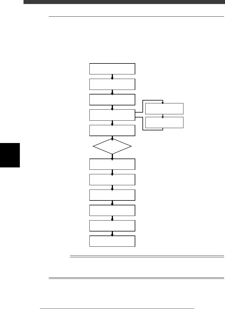
Typical flow chart using the Adjust Assistant commands
23518-C0-00
Select component data
Open Adjust
Assistant screen
Set feeder position
Execute PICK UP COMP.
Execute VISION TEST
Check head & nozzle
to be used
Check pickup/mount
vacuum levels
Execute
DRAW THE SHAPE
Execute PARAM SEARCH
Execute
VISION TEST again
No error
Discard component
Quit Adjust Assistant
ERROR
n
NOTE
The A-table head picks up a component installed in the feeder set positions from No. 1 to
40, while the B-table head picks up a component from the feeder set positions from No.
101 to 140.