YV180X_Ope_E.pdf - 第186页
5 -110 EPD8013110 Operation Chapter 5 5 Creating the PCB data 0 Save the data After all mount data have been checked and corrected, press the [ESC] key to exit the current edit screen, then select <2/1/D8 SA VE PCB DA…
5
-109
EPD8013110
Operation
Chapter 5
5
Creating the PCB data
4 Move the cursor to the first data line on the Mount Info.
screen (left screen).
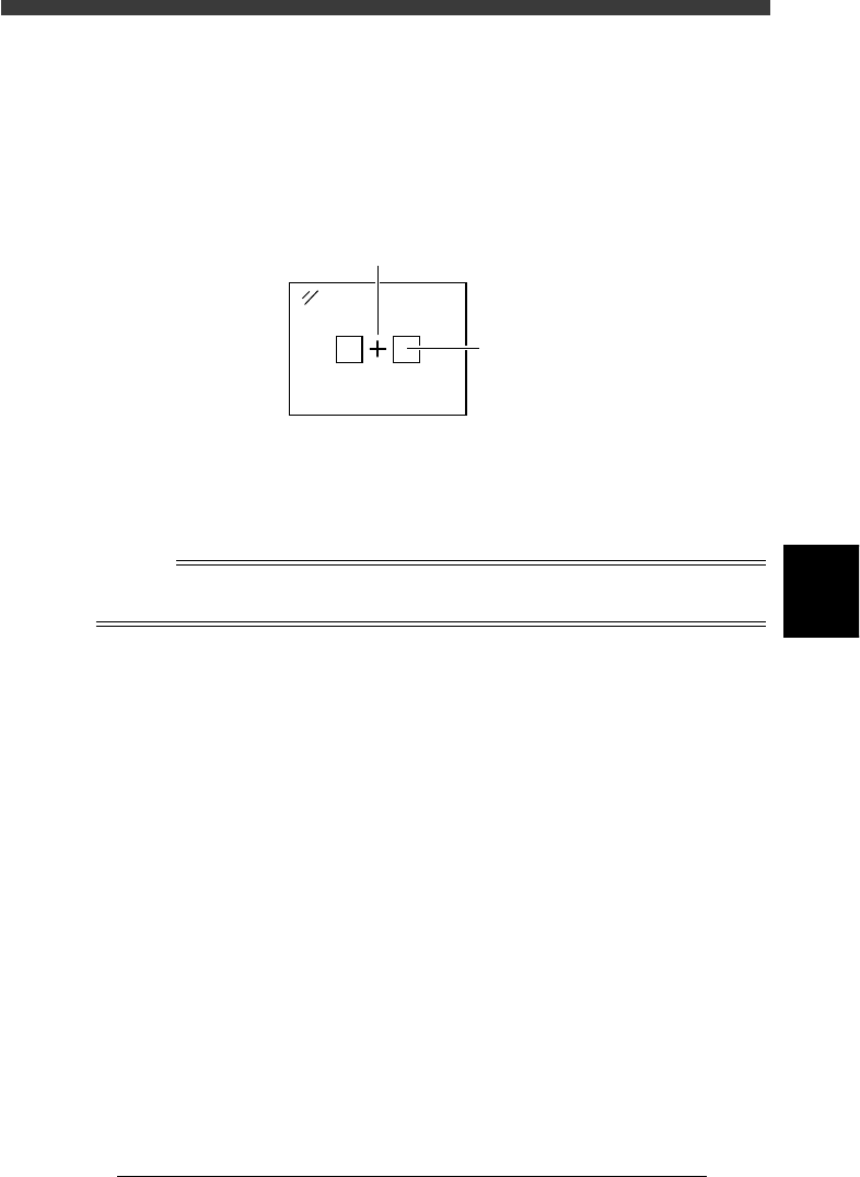
5 Press the [F9] key to check the mounting position by trace.
Pressing the [F9] key starts trace. The camera moves to over the position of
the selected mount data. Check that the cross cursor on the vision monitor
is aligned with the center of the mounting position.
Vision display during trace
23550-C0-00
Cross cursor
Land pattern
6 Correct the XY data.
If the cross cursor on the vision monitor shifts from the center of the
component mounting position, correct the XY data by teaching. Manipu-
late the YPU joystick to move the camera to the center of the mounting
position and press the [F10] key twice to perform teaching.
Reference
If you want to perform teaching input more accurately, use multi-point teaching or vision
cursor teaching. For details, refer to “12. Teaching and trace” in this chapter.
7 Check the land pattern name.
Check that the land pattern name or symbol (ex., R23, U12, etc.) printed
on the PCB matches the land pattern name entered in “SignOfLandPattern”
on the Mount Info. screen. If no land pattern names are entered, enter the
name here. If necessary, use the joystick to move the camera so that the
land pattern name printed on the PCB is brought into view.
8 Check the component number.
Check that the mounting position displayed on the vision monitor and the
component of the input component number are correct. You can refer to
the component No. and name list displayed on the right of the screen.
9 Press the [SHIFT] + [F9] keys to perform trace to the next
point.
The cursor moves down to the next data line to perform another trace.
Check the mounting position in the same manner.
5
-110
EPD8013110
Operation
Chapter 5
5
Creating the PCB data
0 Save the data
After all mount data have been checked and corrected, press the [ESC] key
to exit the current edit screen, then select <2/1/D8 SAVE PCB DATA> and
press the [ENTER] key. If you have changed correct data by mistake, select
<2/1/D9 ABORT PCB DATA> and press the [ENTER] key.
n
NOTE
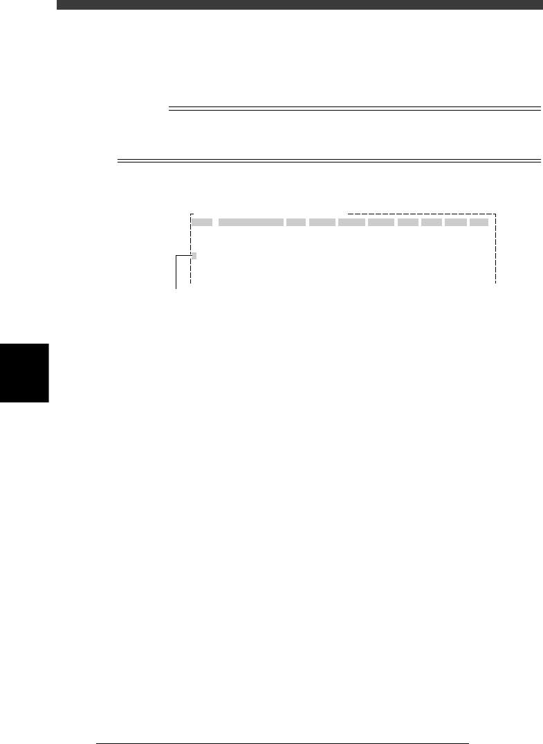
When you press the [Ctrl] + [F9] keys, the cursor moves down to the subsequent data
lines while performing continuous trace, until an empty data line is reached or any key is
pressed. This is called the automatic trace.
Automatic trace screen
27541-C0-00
OBJ :Mount Info.
No.
1
2
3
4
5
SignOfLandPattern
R1005
Comp
1
1
1
1
1
X
10.75
13.75
22.75
22.75
34.75
Y
8.00
9.50
11.00
8.00
8.00
R
0.00
18.00
0.00
0.00
0.00
Head
3
3
3
3
3
FidMk
0
0
0
0
0
Badmk
0
0
0
0
0
Skip?
Exec
Exec
Exec
Exec
Exec
PCB :
The blinking cursor in the No. column shows
the data number being currently traced.
5
-111
EPD8013110
Operation
Chapter 5
5
Creating the PCB data
9. Data optimization
PCB production data you have created can be automatically optimized in
the <2/2/DATA_GENERATOR> mode, so that the PCB data can be used
more efficiently with a minimum cycle time.
For example, to optimize the PCB data on the feeder set position, head
number and mounting sequence, follow the procedure explained in this
section.
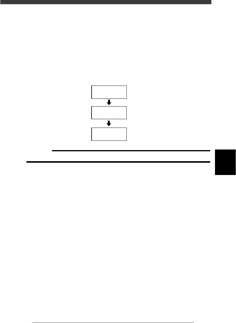
Data optimization flow
23551-C0-00
Set conditions
Select data to be
optimized
Optimize data
9.2
☞
9.1
☞
9.3
☞
c
CAUTION
The PCB data is changed when data optimization is performed.