YV180X_Ope_E.pdf - 第126页
5 -50 EPD8008100 Operation Chapter 5 5 Creating the PCB data ● Editing the BGA ball lead information After you have created BGA component information, you can further edit the ball lead information to improve recognition…
5
-49
EPD8008100
Operation
Chapter 5
5
Creating the PCB data
6. SHAPE INFO. parameters
When “Alignment Type” is set to “Simple BGA”, the following parameters
are displayed in the SHAPE INFO. sub-window.
61. Body Size X, Body Size Y
Enter the correct dimensions measured with a vernier caliper or microme-
ter.
62. Body Size Z
Enter the correct diameter measured with a vernier caliper or micrometer.
63. Dot number N, Dot number E
Enter the number of ball terminals arrayed in the N and E directions. If the
number of terminals per array differs from each other, enter the largest
number of terminals per array.
64. BGA diameter
Enter the diameter of ball terminals.
65. BGA pitch N
Enter the spacing between ball terminals displayed in the N (north)
position of the vision monitor.
66. BGA pitch E
Enter the spacing between ball terminals displayed in the E (east) position
of the vision monitor.
67. Dot amount
Enter the total number of ball terminals of the BGA component.
68. Binary Level
The Comp Threshold parameter is invalid when the Alignment Type
parameter is set to “BGA” or Simple BGA”. Instead, the binary level can
be adjusted with this parameter. For example, if the white portion in the
image appears larger than the actual area, enter a plus value. (For more
details, see “Adjusting the Binary Level” explained later in this section.)
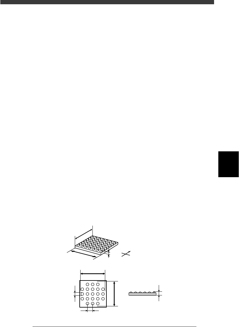
SHAPE INFO. parameters for BGA component
23516-C0-00
N
S
E
W
B
A
C
D
E
F
G
C
A : Body Size X
B : Body Size Y
C : Body Size Z
D : Dot number N
E : Dot number E
F : BGA pitch
G : BGA diamete
r
Side view
Bottom view
5
-50
EPD8008100
Operation
Chapter 5
5
Creating the PCB data
●Editing the BGA ball lead information
After you have created BGA component information, you can further
edit the ball lead information to improve recognition accuracy by using
the Adjust Assistant commands (see “3.7” in this chapter for details on
the Adjust Assistant commands). This is particularly effective in recog-
nizing micro BGA components such as CSP.
1 Open the Adjust Assistant screen of the ball lead compo-
nent.
Line up the cursor with the target component and press the [F6] key to
open the Adjust Assistant screen.
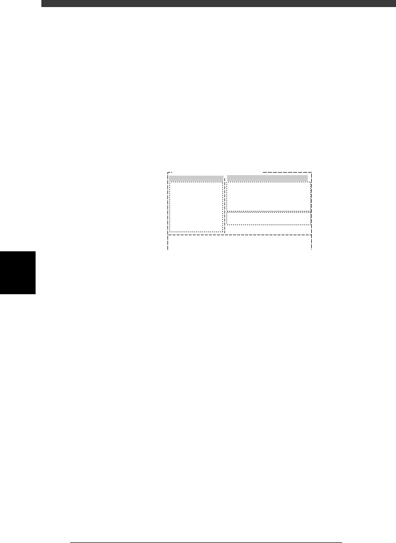
Adjust Assistant screen
27517-C0-00
Comp. Name : BGA_2020
Adjust Assist Items
Feeder set No.
Comp. Tolerance
Comp. Threshold
Lighting Level
Search Area
Monitor Mode
Condition Chk.Mode
25
30
30
8.00
Nothing
ROW
(%)
(mm)
6 / 8
Command
PICK UP COMP.
*
VISION TEST
PARM. SEARCH
DISCARD COMP.
DRAW THE SHAPE
CHK GRAY VALUE
EXIT
2 Set the Feeder Set No. and Monitor Mode parameters.
Press the right arrow key to move the cursor into the Adjust Assistant Items
window, and set the Feeder Set No. and Monitor Mode parameters as
follows.
Feeder Set No. : Set to a feeder position where you can easily attach
the component by hand.
Monitor Mode : Nothing
3 Execute the PICK UP COMP. command.
Press the left arrow key to move the cursor back to the command list
screen (left-hand screen), then execute the PICK UP COMP. command.
e
The head assembly moves to the feeder position specified in the Feeder Set
No. After the head assembly stops, press the emergency stop button and
then attach the component to the nozzle tip by hand.
4 Execute the VISION TEST command.
Cancel emergency stop, then execute the VISION TEST command.
The image currently displayed on the vision monitor is reset.
5 Execute the DRAW THE SHAPE command.
Follow the utility messages displayed on the operation monitor to open the
screen for editing the BGA ball lead information, which will appear on the
upper left of the vision monitor.
5
-51
EPD8008100
Operation
Chapter 5
5
Creating the PCB data
Utility messages for editing the BGA ball lead information
27518-C0-00
V400
[BGA BALL DATA UTILITY]
Please select command.
(1) [Enter] key :[EDIT & REGISTRATION]
(2) [Tab] key :[DELETE DATA]
(3)any other key :[EXIT]
V401
There is no data for this component.
Do you make new data and edit it?
Please select.
[Enter] key :EXEC
any other key :CANCEL
V413
[BGA ball data edit] will e executed
on vision monitor.
To start to edit, please press any key.
V404
How to edit [BGA ball data]
[Arrow] key :move cursor
[Space] key :one ball ON/OFF
[F1] key :horizontal line all ON
[F2] key :vertical line all ON
[F3] key :horizontal line all OFF
[F4] key :vertical line all OFF
[Enter] key :exit
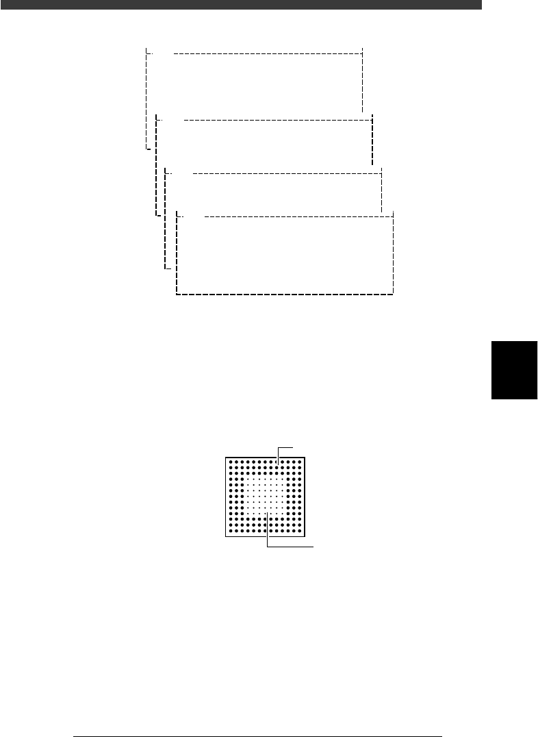
6 Edit the ball lead position data.
When the BGA ball lead information edit screen appears on the upper left
of the vision monitor, edit it while referring to the utility messages
displayed on the operation monitor, so that the ball lead display on the
edit screen exactly matches the ball lead arrangement of the actual
component. The ball lead display should be set to ON at positions where
the ball lead exists and to OFF where it does not exist.
BGA ball lead information edit screen
21501-C0-00
Hn:13
Vn:13
N: 0
nh:1
nv:1
ON
OF
F