YV180X_Ope_E.pdf - 第129页
5 -53 EPD8008100 Operation Chapter 5 5 Creating the PCB data ● Adjusting the Binary Level If the mold part of the BGA package reflects light during recognition of the ball leads, the reflected light may be misdetected as…
5
-52
EPD8008100
Operation
Chapter 5
5
Creating the PCB data
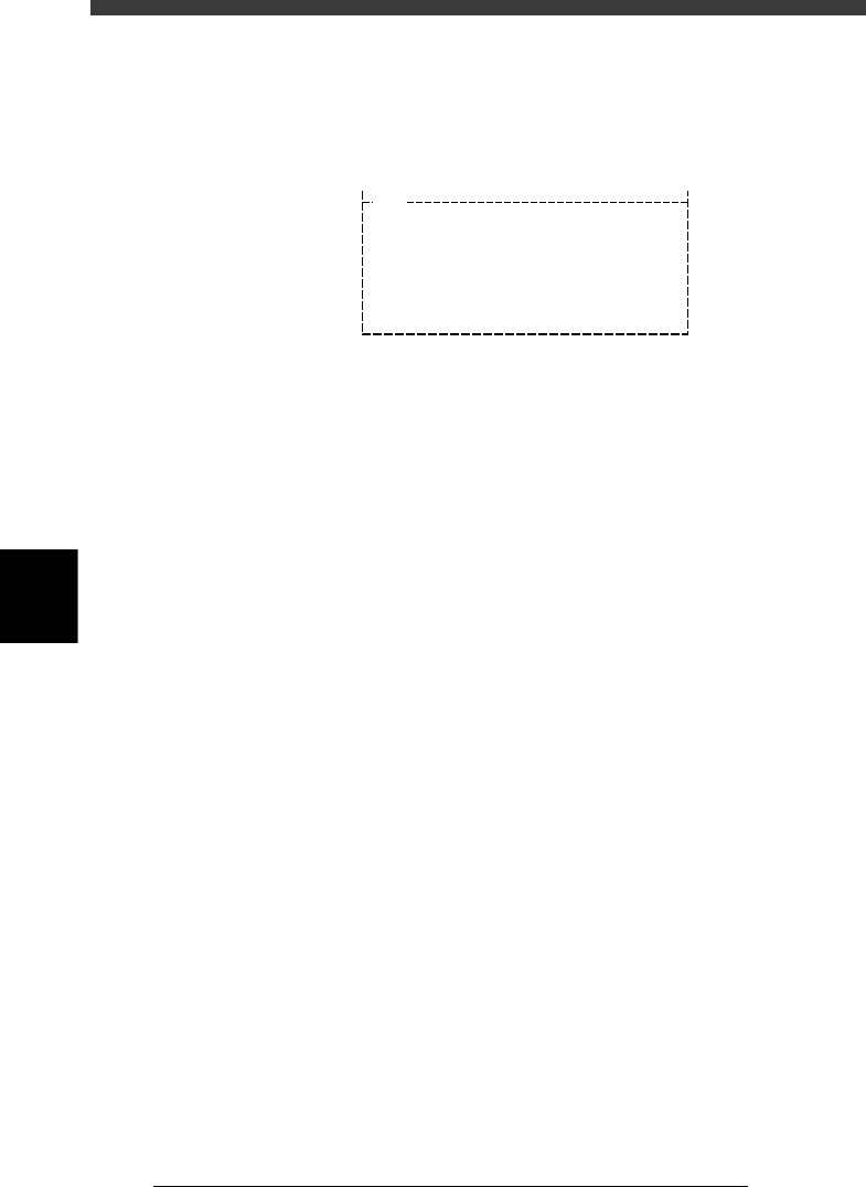
7 Register the edited data.
When you have edited the ball lead information, press the [ENTER] key to
register the edited data in the BGA ball data registration boxes. Follow the
messages displayed on the operation monitor to complete the registration.
BGA ball data registration boxes
27519-C0-00
V400
[BGA BALL DATA UTILITY]
Please select command.
(1) [Enter] key :[EDIT & REGISTRATION]
(2) [Tab] key :[DELETE DATA]
(3) any other key :[EXIT]
8 Execute the VISION TEST commands again.
Repeat the VISION TEST command a few times. If no error occurs, the
BGA ball lead data is appropriate. Execute the PICK UP COMP command
to remove the component from the nozzle, the DISCARD COMP com-
mand to turn off the vacuum generation, and the EXIT command to quit
the Adjust Assistant mode.
If an error occurs, proceed to the next section “Adjusting the Binary
Level”.
5
-53
EPD8008100
Operation
Chapter 5
5
Creating the PCB data
●Adjusting the Binary Level
If the mold part of the BGA package reflects light during recognition of the
ball leads, the reflected light may be misdetected as a lead, resulting in a
ball lead recognition error. To avoid this type of error, increasing the ball
lead area will prove effective.
1 Set the Monitor Mode parameters to “FINE LINE”.
Press the right arrow key to move the cursor to the Adjust Assistant Items
window, then set the Monitor Mode parameter to “FINE LINE”.
2 Execute the VISION TEST command.
Press the left arrow key to move the cursor back to the command window,
then execute “VISION TEST”.
If the mold part of the BGA is displayed in white on the vision monitor,
you will need to adjust the binary level as described below.
3 Press the [TAB] key to move the cursor into the sub-
window of the component information.
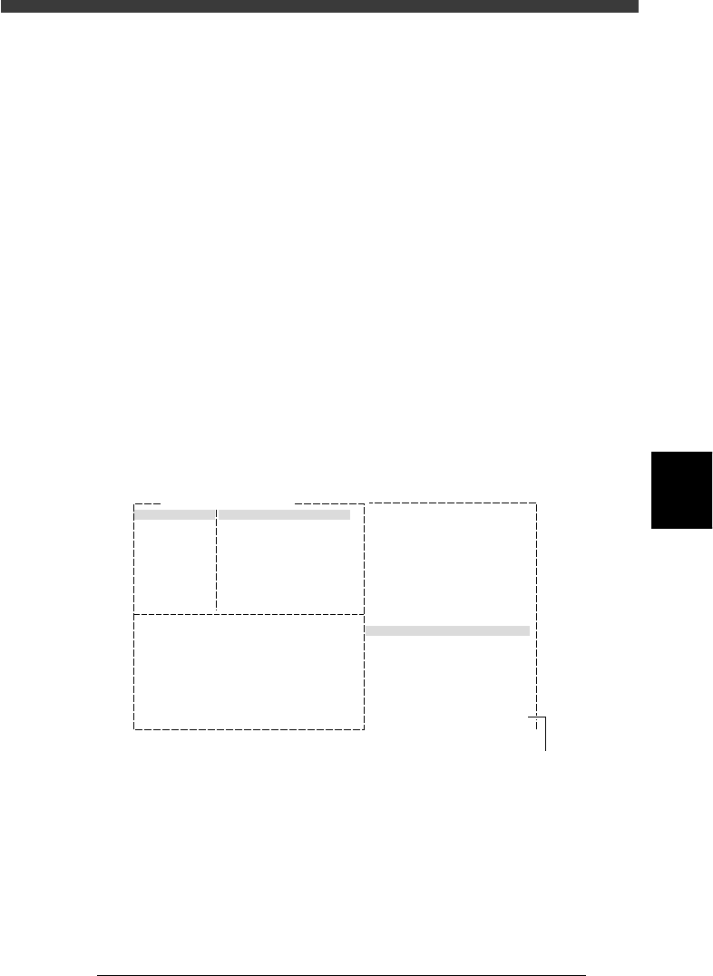
4 Adjust the Binary Level value in the SHAPE INFO.
subwindow.
Enter a value which is estimated from the percentage of the mold part area
displayed in white versus the entire area of the ball leads.
Binary Level adjustment
27520-C0-00
6. SHAPE INFO.
Binary Level
:
:
:
:
:
:
:
:20
Comp. Name : BGA
Adjust Assistant Items
Monitor Mode Find Line
Command
VISION TEST
Binary level settin
g
5 Repeat the VISION TEST command.
When no error occurs, the binary level is correct.
6 Save the settings.
Exit the Adjust Assistant mode, then press the [ESC] key twice, select <2/1/
D8 SAVE PCB DATA> and press the [ENTER] key.
5
-54
EPD8008100
Operation
Chapter 5
5
Creating the PCB data
3.6 Connector components
3.6.1 Connectors
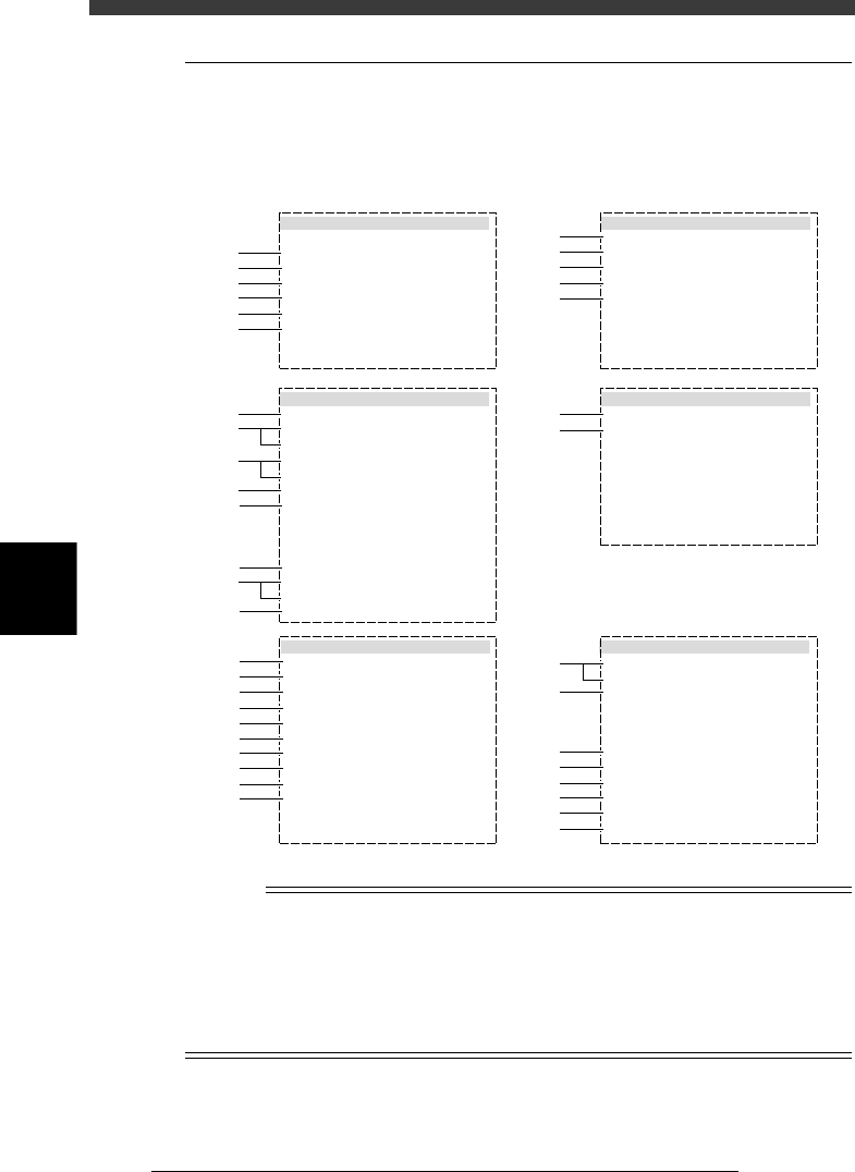
Connector components are registered with the parameters shown below.
Connector component parameters
27521-D8-00
6.SHAPE INFO.
Body Size X
Body Size Y
Body Size Z
Cntr.OffsetX
Cntr.OffsetY
Cntr.OffsetR
Ruler Offset
Ruler Width
Lead Number
ReflectLL. E
LeadWidth E
LeadPitch E
:
:
:
:
:
:
:
:
:
:
:
:
5.10
28.00
0.30
0.00
0.00
0.00
3
3
40
0.00
0.20
0.50
5.VISION INFO.
Alignment Group
Alignment Type
AlignmentModule
Light Selection
Lighting Level
Comp. Threshold
Comp. Tolerance
Search Area mm
Datum Angle
Comp. Intensity
MultiCam. Marker
:
:
:
:
:
:
:
:
:
:
:
Connector
Con-E
Fore&Back&Las
Main + Coax
6/8
Normal
NotUse
30
30
1.50
0
1.BASIC INFO.
Database No.
Comp. Package
Feeder Type
Required Nozzle
Feeder Set No.
Pos. Definition
Feeder Pos_X mm
:
:
:
:
:
:
:
Tape
44mmEmboss
Sp.NozzleA
Automatic
851
8
6.20
2.OPTION INFO.
FixCmpRef.
AIt.Cmp
Use feeder opt.
Comp. Group No.
Correct Pickpos
:
:
:
:
:
Yes
Not Use
0
0
0
3.PICK AND MOUNT INFO.
Pick Angle deg
Pick Timer
Mount Timer
Pick Height
Mnt Height
Pick Sequence
Mount Action
Mount Speed
PickupSpeed
XY Speed
Vacuum Check
Pick Vacuum
Mount Vacuum
Conv. Y Speed
:
:
:
:
:
:
:
:
:
:
:
:
:
:
4.DUMP INFO.
Dump Way
Retry Times
:
:
Dump POS
2
s
s
mm
mm
%
%
%
%
%
0
0.15
0.05
Normal
NORMAL
100
100
100
NORMAL CHK
FAST
0.0
0.0
10
10
mm
mm
mm
mm
mm
E
E
mm
mm
mm
1
2
3
4
5
6
41
42
43
44
45
46
47
48
49
50
51
11
12
13
14
15
31
32
61
62
63
64
64
65
66
67
21
22
23
24
25
26
27
28
n
NOTE
When setting the parameters shown in the sub-windows above, use the number keys to set
the parameters aligned on the right, while using the [INS], [DEL] or [Space] key to set
the parameters aligned on the left. However, there are some parameters which should be
set or optimized with the Adjust Assistant commands described later in “3.7” in this
chapter.
The displayed parameters differ slightly depending on the <3/1/A1 OPTION CONFIG>
settings.