YV180X_Ope_E.pdf - 第119页
5 -43 EPD8008100 Operation Chapter 5 5 Creating the PCB data 1. BASIC INFO. parameters 1. Comp. Package Refer to the description in “ 3.3.1 Standard chip components ” . 2. Feeder T ype Refer to the description in “ 3.3.1…
5
-42
EPD8008100
Operation
Chapter 5
5
Creating the PCB data
3.5 Ball lead components
When creating ball lead component data such as BGA, there are two
choices of setting “Alignment Type” in the VIOSN INFO. sub-window:
“Simple BGA” and “BGA”.
3.5.1 Simple BGA
When the Alignment Type parameter is set to “Simple BGA”, BGA
components are registered with the parameters shown below. With this
setting, the BGA arrangement and nicked leads are not checked. To check
them, the Alignment Type parameter shoulde be set to “BGA”. (See the
next section “3.5.2 BGA”.
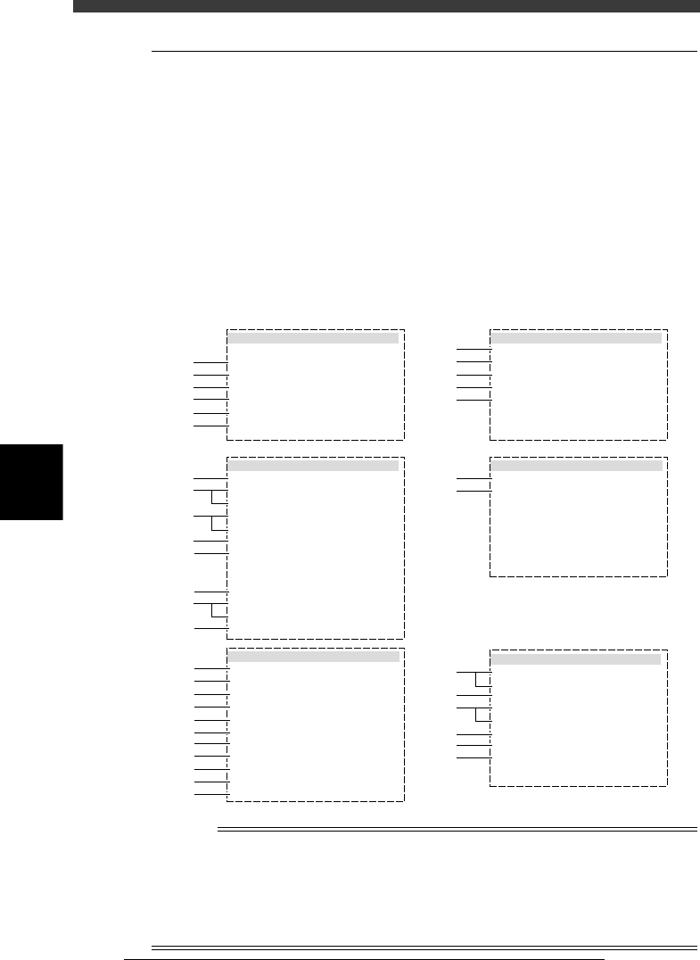
BGA parameters (when Alignment Type is set to “Simple BGA”)
27515-D8-00
6.SHAPE INFO.
Body Size X
Body Size Y
Body Size Z
Dot number N
Dot number E
BGA diameter
BGA pitch
Dot amount
:
:
:
:
:
:
:
:
23.00
23.00
1.80
13
13
0.75
1.50
169
5.VISION INFO.
Alignment Group
Alignment Type
AlignmentModule
Light Selection
Lighting Level
Comp. Threshold
Comp. Tolerance
Search Area mm
Datum Angle
Comp. Intensity
MulriCam. Marker
:
:
:
:
:
:
:
:
:
:
:
Ball
Simple BGA
Fore
Main + Coax
4/8
Non effective
Norma
NotUsel
30
1.50
0
1.BASIC INFO.
Database No.
Comp. Package
Feeder Type
Required Nozzle
Feeder Set No.
Pos. Definition
Feeder Pos_X mm
:
:
:
:
:
:
:
Tape
32mmEmboss
ForQFP30mm 74
Teaching
950
7
-16.00
2.OPTION INFO.
FixCmpRef.
AIt.Cmp
Use feeder opt.
Comp. Group No.
Correct Pickpos
:
:
:
:
:
Yes
Not Use
0
0
0
3.PICK AND MOUNT INFO.
Pick Angle deg
Pick Timer
Mount Timer
Mnt Height
Pick Sequence
Mount Action
Mount Speed
PickupSpeed
XY Speed
Vacuum Check
Pick Vacuum
Mount Vacuum
Conv. Y Speed
:
:
:
:
:
:
:
:
:
:
:
:
:
4.DUMP INFO.
Dump Way
Retry Times
:
:
Dump POS
2s
s
mm
%
%
%
%
%
0
0.30
0.20
Normal
QFP
30
100
100
SPECIAL CHK
FAST
0.0
10
10
mm
mm
mm
mm
mm
1
2
3
4
5
6
41
42
43
44
45
46
47
48
49
50
51
11
12
13
14
15
31
32
61
62
63
64
64
65
21
22
23
24
25
26
27
28
29
n
NOTE
When setting the parameters shown in the sub-windows above, use the number keys to set
the parameters aligned on the right, while using the [INS], [DEL] or [Space] key to set
the parameters aligned on the left. However, there are some parameters which should be
set or optimized with the Adjust Assistant commands described later in “3.7” in this
chapter.The displayed parameters differ slightly depending on the <3/1/A1 OPTION
CONFIG> settings.

5
-43
EPD8008100
Operation
Chapter 5
5
Creating the PCB data
1. BASIC INFO. parameters
1. Comp. Package
Refer to the description in “3.3.1 Standard chip components”.
2. Feeder Type
Refer to the description in “3.3.1 Standard chip components”.
3. Required Nozzle
Select the optimum nozzle that matches the component size from among
the nozzle types for QFP components. (See “Nozzle table” listed in
Supplement in this manual.)
4. Feeder Set No.
Refer to the description in “3.3.1 Standard chip components”.
5. Pos. Definition
Refer to the description in “3.3.1 Standard chip components”.
6. Feeder Pos_X
Refer to the description in “3.3.1 Standard chip components”.
2. OPTION INFO. parameters
For descriptions of the following OPTION INFO. parameters, refer to
“3.3.1 Standard chip components” in this chapter.
11. FixCmpRef.
12. Alt. Comp.
13. Use feeder opt.
14. Comp. Group No.
15. Correct Pickpos.
3. PICK & MOUNT INFO. parameters
21. Pick Angle deg
Use the same setting as for QFP components.
22. Pick Timer, Mount Timer
Refer to the description in “3.4.2 SOP component”.
23. Pick Height, Mount Height
Refer to the description in “3.3.1 Standard chip component”.
24. Pick Sequence
Refer to the description in “3.3.1 Standard chip component”.
25. Mount Action
Set this parameter to “QFP” when mounting accuracy is more important
than operation speed. (Refer to the description in “3.3.4 QFP components”
for detail.)
26. Vacuum Check
Set this parameter to “SPECIAL CHK” in most cases. (Refer to the
description in “3.3.4 QFP components” for detail. )

5
-44
EPD8008100
Operation
Chapter 5
5
Creating the PCB data
27. Pick Vacuum, Mount Vacuum
These are reference vacuum pressures used for checking the pickup and
mount vacuum levels. Use the default settings and adjust them as needed
in the Adjust Assistant mode. (See “3.7” in this chapter.)
28. Conv. Y Speed
Refer to the description in “3.3.1 Standard chip components”.
4. DUMP INFO. parameters
31. Dump Way
Set to “Station” when a dump station (option) is used and to “Dump POS.”
when not used. Refer to the Discard point parameter explained in the
mounter service manual.
32. Retry Times
Refer to the description in “3.3.1 Standard chip components”.
5. VISION INFO. parameters
41. Alignment Group
Set to “Ball”.
42. Alignment Type
Use the default setting “Simple BGA”.
43. AlignmentModule
This parameter specifies the lighting method for recognizing a component.
Use the default setting (Fore).
44. Light Selection
Set to “Main+Coax” when editing the ball lead arrangement. When you
want to check nicked ball leads, set this parameter to “Only Side”.
For descriptions of the following VISION INFO. parameters, refer to
“3.3.1 Standard chip components”.
45. Lighting Level
46. Comp. Threshold
This parameter is skipped for BGA components.
47. Comp. Tolerance
48. Search Area
49. Datum Angle
50. Comp. Intensity
51. MultiCam. Marker