YV180X_Ope_E.pdf - 第196页
5 -120 EPD8013110 Operation Chapter 5 5 Creating the PCB data e 3. Press the emergency stop button, and set the PCB on the conveyor to confirm that the width is correct. If not correct, quit automatic opera- tion by exec…
5
-119
EPD8013110
Operation
Chapter 5
5
Creating the PCB data
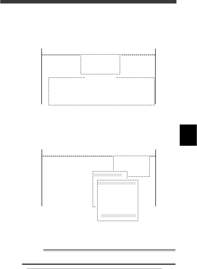
3 Check the conveyor setups as follows.
Run <1/1/B6 RUNNING CONDITION> and check the PCB clamping
method (PcbFixDevice). If you want to change the PCB clamping method,
move the cursor to “PcbFixDevice”, select the desired setting with the
[INS], [DEL] or [SPACE] key, and press the [ENTER] key.
Running Condition Editor box
27550-C0-00
<<MODE>> 1/RUNNING
<COMMAND LIST>
B/CONDITION
B6 RUNNING CONDITION
PcbFixDevice Pin+PushUP
Running Condition Editor
2 Set up the conveyor units.
1. Run the <1/1/D4 ASSISTANT UTILITY> - “CONVEYOR UNITS”
command.
The CONVEYOR UNIT menu box appears.
CONVEYOR UNIT menu box
27551-C0-00
OFF
ON
OFF
OFF
OFF
OFF
OFF
OFF
OFF
OFF
CONVEYOR UNIT (STS.)
LOCATE PIN
PUSH UP
PCB CLAMP
EDGE CLAMP
PUSH IN
MAIN STOPPER
ENT. STOPPER
EXIT STOPPER
CONV. MOTOR
CONV. WIDTH
PROGRAM PIN
RETURN
<<MODE>> 1/RUNNING
<COMMAND_LIST>
D/INITIALIZE
D4 ASSISTANT UTILITY
ASSISTANT UTILITY
CONVEYOR UNITS
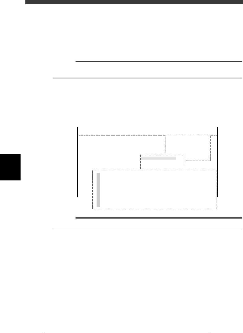
2. From the CONVEYOR UNIT menu box, select “CONVEYOR WIDTH”
and press the [ENTER] key.
The conveyor width is automatically adjusted according to the “PCB
Size” Y data in the PCB Information.
w
WARNING
UPON EXECUTING THE “CONVEYOR WIDTH” COMMAND, THE CONVEYOR
RAIL BEGINS TO MOVE, SO USE CAUTION.
5
-120
EPD8013110
Operation
Chapter 5
5
Creating the PCB data
e
3. Press the emergency stop button, and set the PCB on the conveyor to
confirm that the width is correct. If not correct, quit automatic opera-
tion by executing the <1/1/E0 EXIT FROM RUNNING> command, then
select <1/2/PRD. DATA> - ”PCB Info.” to correct the “PCB Size” Y data.
4. After checking the conveyor width, adjust the locate pin and push-up
pin positions so that the PCB can be clamped on the conveyor. Finally,
remove the PCB.
Reference
Refer to “8. Changing the conveyor unit setup” in Chapter 4 for details on the conveyor
unit setups.
4 Set up the components (feeder set).
Run the <1/1/D4 ASSISTANT UTILITY> command, and select “COMPO-
NENT ASSIGNMENT” to check the setup of the components. A list of
feeder mounting positions appears as shown below.
COMPONENT ASSIGNMENT screen
27552-C0-00
No.
15
12
7
13
1
9
5
17
Feeder Type
8mmTape
8mmTape
8mmTape
8mmTape
8mmTape
8mmTape
8mmTape
8mmTape
Component Name
MINI_TR
MINI_TR
R2125
R3126
R1608
R1608
R2125
MINI_TR
SetNo.
F9
F10
F11
F12
F13
F14
F15
F16
Counter / Total
↑
↓
<<MODE>> 1/RUNNING
<COMMAND_LIST> D/INITIALIZE
D4 ASSISTANT UTILITY
ASSISTANT UTILITY
COMPONENT ASSIGNMENT
Reference
For details on the component setups, refer to the separate feeder user’s manual.
5
-121
EPD8013110
Operation
Chapter 5
5
Creating the PCB data
10.2 Starting the test mount
Now, try producing only one PCB to check how components are mounted.
We recommend using a PCB with double-sided tape affixed across the
mounting position.
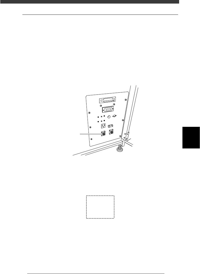
1 Unplug the PREVIOUS INTERFACE connector
When the mounter is installed on a production line, unplug the GATE-IN
(PREVIOUS INTERFACE) connector on the lower right panel on the front of
the machine. If you perform a mounting test with this connector still
plugged, the PCB may flow into the downstream process after component
mounting, or the PCB may drop.
GATE-IN (PREVIOUS INTERFACE) connector
23553-D8-00
PREVIOUS
INTERFACE
2 Set the operation speed.
Press the [SPEED] key on the YPU, or select the <1/1/D6 RUNNING
UTILITY> - ”RUNNING SPEED” command, then set the speed to approx.
40 to 60%.
Speed setting box
27553-C0-00
Spead1 =
Spead2 =
Spead3 =
Spead4 =
Spead5 =
100
80
60
40
20