YV180X_Ope_E.pdf - 第153页
5 -77 EPD8013110 Operation Chapter 5 5 Creating the PCB data Mark T ype Info. parameters 1. Mark T ype The “Mark T ype” parameter in the Mark T ype Info. sub-window should be set to “Fiducial”. Vision Info. parameters 2.…
5
-76
EPD8013110
Operation
Chapter 5
5
Creating the PCB data
4.2 Various parameter settings
This section describes how to set basic parameters in the mark information
sub-windows. Parameter settings not explained here should be found by
evaluating recognition results obtained with the Adjust Assistant or refer-
ring to the help message displayed by pressing the [F1] key.
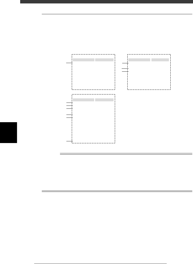
Parameters for fiducial mark setting
27533-D8-00
Mark Type Info.
Edit Term
Mark Type
DataBase Number
:
:
:
Fiducial
297
Mark size Info.
Edit Term
MarkOutSizeX
MarkOutSizeY
Area
Perimeter
:
:
:
:
:
1.50
1.50
1.77
4.71
Vision Info.
Edit Term
Shape Type
Surface Type
Algorithm Type
Mark Threshold
Tolerance
Search Area
Outer Light
Inner Light
Coaxial Light
IR Outer Light
IR Inner Light
Cut Inner Noise
Cut Outer Noise
Sequence
:
:
:
:
:
:
:
:
:
:
:
:
:
:
:
Sp. Shape
Reflect
Normal
Standard + 1
Standard + 1
Standard + 1
OFF
Standard + 1
0
0
Normal
115
30
3.00
1
2
3
4
5
6
7
8
9
10
n
NOTE
When setting the parameters shown in the sub-windows above, use the number keys to set
the parameters aligned on the right, while using the [INS], [DEL] or [Space] key to set
the parameters aligned on the left. However, there are some parameters which should be
set or optimized with the Adjust Assistant commands described later in “3.7” in this
chapter.
The Area and Perimeter parameters in the Mark Size Info. sub-window are displayed only
when the Shape parameter in the Vision Info, sub-window is set to “Sp. Shape”.
5
-77
EPD8013110
Operation
Chapter 5
5
Creating the PCB data
Mark Type Info. parameters
1. Mark Type
The “Mark Type” parameter in the Mark Type Info. sub-window should be
set to “Fiducial”.
Vision Info. parameters
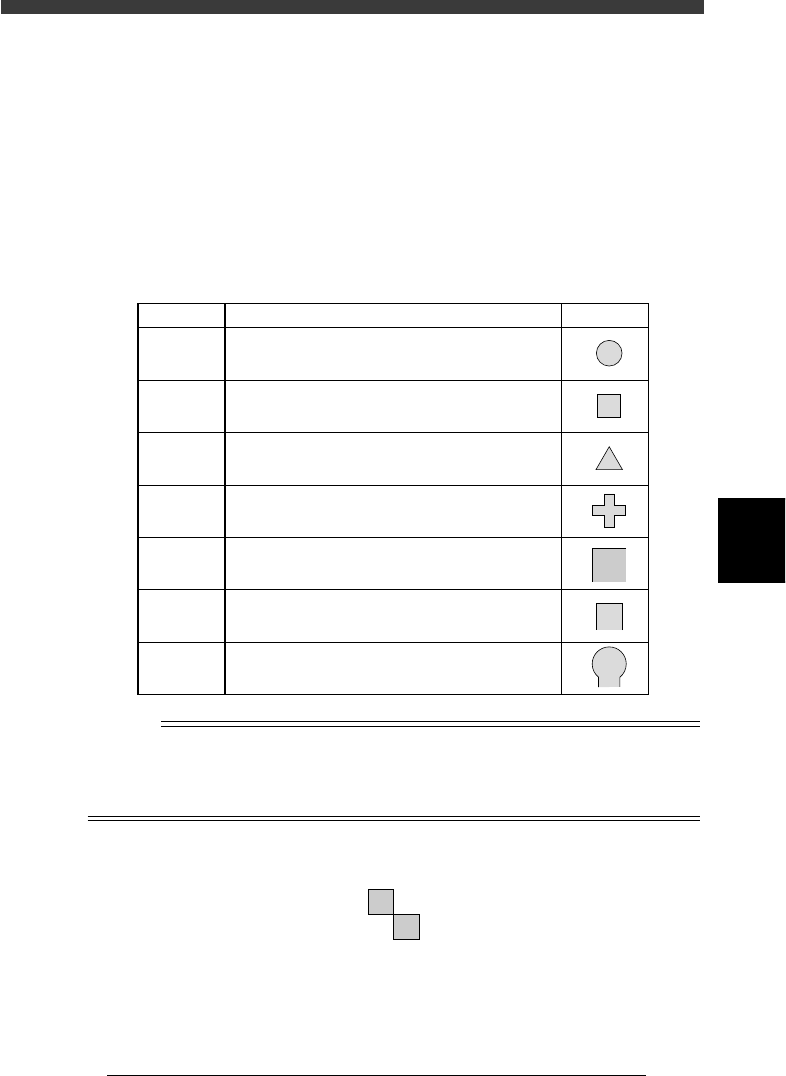
2. Shape Type
The Shape Type in the Vision Info. sub-window can be selected from the
following 7 types.
Shape Type settings
25512-C0-00
Setting Description
Example
Circle
Square
Triangle
Sp. Shape
Corner
TopEdge
CirEdge
Select to detect a circular mark.
Select to detect a square mark.
Select to detect an equilateral triangular mark.
Select to detect a special mark other than above.
Select to detect a corner of a pattern as a mark.
Select to detect an edge of a pattern as a mark.
This setting is effective in detecting a square edge.
Select to detect an edge of a pattern as a mark.
This setting is effective in detecting a round edge.
Reference
If you use a special mark composed of two or more objects as shown below, set the
Algorithm Type parameter (described later) to “Pattern”. In this case, the “Shape”
parameter is ignored during recognition, so you can set this parameter to any type. (For
more details, see “9. Pattern matching” in Chapter 6.)
Example of special mark
21502-C0-00
5
-78
EPD8013110
Operation
Chapter 5
5
Creating the PCB data
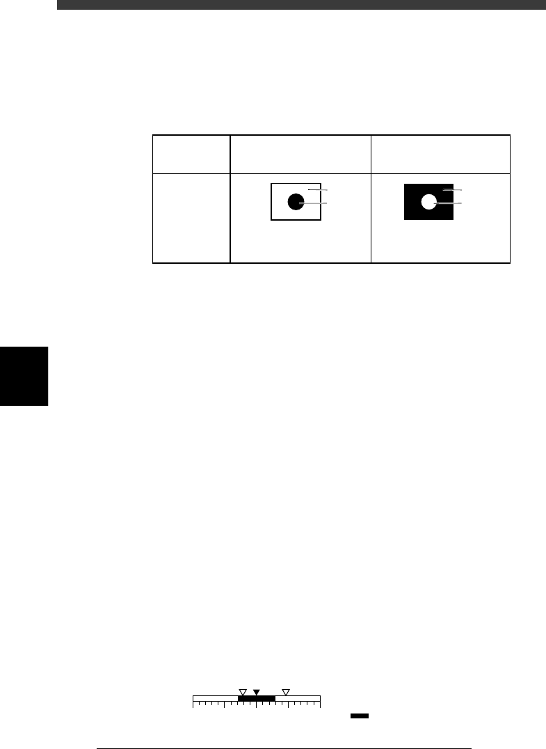
3. Surface Type
This specifies the bright and dark relation between the mark surface and
PCB (surrounding area). Select “NonReflect” when the mark is darker than
the surrounding area, and select “Reflect” when the mark is brighter than
the surrounding area, as shown below.
Surface Type settings
25513-C0-00
NonReflect
PCB is brighter than mark.
Reflect
Mark is brighter than PCB.
Parameter
setting
Displayed
image
PCB
Mark
PCB
Mark
4. Algorithm Type
There are 5 algorithm types selectable for mark recognition.
• Normal
In typical recognition, all types of marks should be set to “Normal”. Try
setting to other parameters if the mark cannot be recognized with the
“Normal” setting.
• Special 1
Select this if the mark cannot be recognized by the “Normal” setting.
• Special 2
Select this if the mark which cannot be recognized by the “Normal”
setting has a cutout area.
• PTRN Outline, PTRN GrayLev
Select these parameters when the Shape Type parameter is set to
“Pattern”. For more details, refer to “9. Pattern matching” in Chapter 6.
5. Tolerance
This specifies a tolerance percentage for the mark size when the mark is
recognized with the vision system. (Typically this should be set to “30”.)
For example, suppose as shown below that the tolerance is set to 30 (%)
with respect to point A representing the mark size setting, and points B and
C are the actually measured mark sizes. Point B is okay since it is recog-
nized within the allowable range, but point C is treated as an error since it
is outside the allowable range.
Tolerance
23530-C0-00
0
ABC
+100 (%)-100
A: Mark size setting
B, C: Vision recognition result
: Allowable range