YV180X_Ope_E.pdf - 第102页
5 -26 EPD8008100 Operation Chapter 5 5 Creating the PCB data 6. SHAPE INFO. parameters Set these parameters after specifying the VISION INFO. parameters. If “ Alignment T ype ” is undefined, the follo wing par ameters ar…

5
-25
EPD8008100
Operation
Chapter 5
5
Creating the PCB data
For descriptions of the following PICK & MOUNT INFO. parameters,
refer to “3.3.1 Standard chip components” in this chapter.
22. Pick Timer, Mount Timer
23. Pick Height, Mount Height
24. Pick Sequence
25. Mount Action
26. Vacuum Check
27. Pick Vacuum, Mount Vacuum
These are reference vacuum pressures used for checking the pickup and
mount vacuum levels. For more details, see “3.7 Adjust Assistant com-
mands“ and “3.9 Pickup and mount vacuum pressures” in this chapter.
28. Conv. Y Speed
4. DUMP INFO. parameters
31. Dump Way
Set to “Dump POS”. Refer to the Discard point parameter explained in the
mounter service manual.
32. Retry Times
See the description of “3.3.1 Standard chip components”.
5. VISION INFO. parameters
41. Alignment Group
Set this parameter to “Chip”.
42. Alignment Type
Set this parameter to “Melf Chip”.
43. AlignmentModule
This parameter specifies the lighting method for recognizing a component.
Use the default setting (Fore&Back&Laser) in most cases. Refer to the
description in “3.3.1 Standard chip components” for more details.
For descriptions of the following VISION INFO. parameters, refer to
“3.3.1 Standard chip components”.
44. Light Selection
45. Lighting Level
46. Comp. Threshold
47. Comp. Tolerance
48. Search Area
49. Datum Angle
50. Comp. Intensity
51. MultiCam Marker
5
-26
EPD8008100
Operation
Chapter 5
5
Creating the PCB data
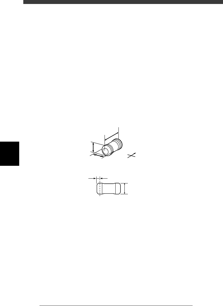
6. SHAPE INFO. parameters
Set these parameters after specifying the VISION INFO. parameters. If
“Alignment Type” is undefined, the following parameters are not dis-
played.
61. Body Size X, Body Size Y
Enter the correct dimensions including the leads, measured with a vernier
caliper or micrometer.
62. Body Size Z
Enter the correct thickness measured with a vernier caliper or micrometer.
63. Ruler Offset
Refer to “3.3.1 Standard chip components” in this chapter.
64. Lead Width
Enter the width of the leads provided on both ends of the component. (See
the drawing below.) This can be checked by executing the Adjust Assistant
explained later.
SHAPE INFO. parameters for Melf components
23509-C0-00
N
S
E
W
C
E
D
A
B
A : Body Size X
B : Body Size Y
C : Body Size Z
D : Ruler Offset
E : Lead Width
5
-27
EPD8008100
Operation
Chapter 5
5
Creating the PCB data
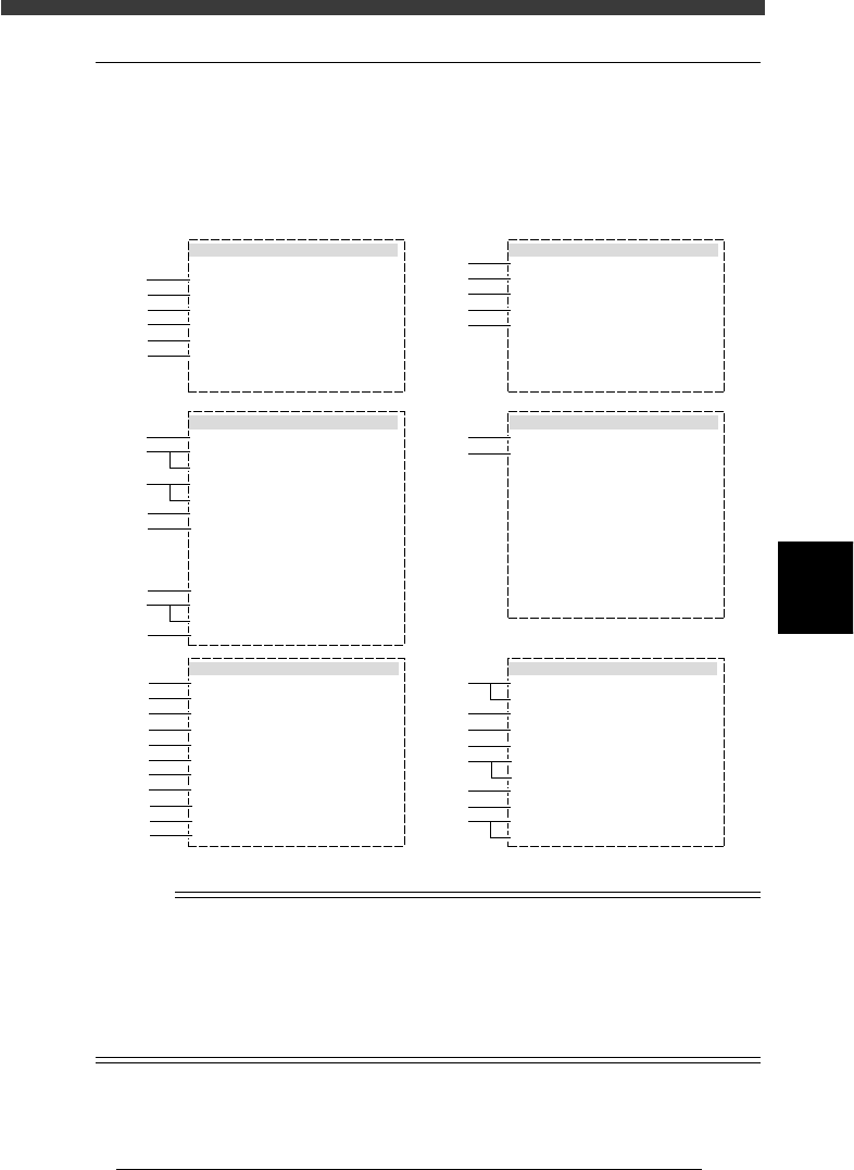
3.4 IC components
3.4.1 Mini-mold transistor/SOT
Mini-mold transistors and SOT components are registered with the param-
eters shown below.
Mini-mold transistor parameters
27512-D8-00
6. SHAPE INFO.
Body Size X mm
Body Size Y mm
Body Size Z mm
Ruler Offset
Ruler Width
Lead Number N
Lead Number S
ReflectLL. mm
LeadWidth mm
LeadPitch N mm
LeadPitch S mm
:
:
:
:
:
:
:
:
:
:
:
2.90
2.80
1.10
3
2
2
1
0.30
0.50
1.75
1.75
5. VISION INFO.
Alignment Group
Alignment Type
AlignmentModule
Light Selection
Lighting Level
Comp. Threshold
Comp. Tolerance
Search Area mm
Datum Angle
Comp. Intensity
MultiCam. marker
:
:
:
:
:
:
:
:
:
:
:
IC
Mini-Tr/SOT
Fore&Back&Las
Main + Coax
6/8
Normal
NotUse
30
30
1.50
0
1. BASIC INFO.
Database No.
Comp. Package
Feeder Type
Required Nozzle
Feeder Set No.
Pos. Definition
Feeder Pos_X mm
:
:
:
:
:
:
:
Tape
32mmEmboss
For2125Chp72
Automatic
602
12
71.79
2. OPTION INFO.
FixCmpRef.
AIt.Cmp
Use feeder opt.
Comp. Group No.
Correct Pickpos
:
:
:
:
:
Yes
Not Use
0
0
0
3. PICK AND MOUNT INFO.
Pick Angle deg
Pick Timer
Mount Timer
Pick Height
Mnt Height
Pick Sequence
Mount Action
Mount Speed
PickupSpeed
XY Speed
Vacuum Check
Pick Vacuum
Mount Vacuum
Conv. Y Speed
:
:
:
:
:
:
:
:
:
:
:
:
:
:
4. DUMP INFO.
Dump Way
Retry Times
:
:
Dump POS
2
s
s
mm
mm
%
%
%
%
%
0
0.00
0.00
Normal
NORMAL
100
100
100
NORMAL CHK
FAST
0.0
0.2
30
30
1
2
3
4
5
6
41
42
43
44
45
46
47
48
49
50
51
11
12
13
14
15
31
32
61
62
63
64
64
65
66
67
21
22
23
24
25
26
27
28
29
n
NOTE
When setting the parameters shown in the sub-windows above, use the number keys to set
the parameters aligned on the right, while using the [INS], [DEL] or [Space] key to set
the parameters aligned on the left. However, there are some parameters which should be
set or optimized with the Adjust Assistant commands described later in “3.7” in this
chapter.
The displayed parameters differ slightly depending on the <3/1/A1 OPTION CONFIG>
settings.