YV180X_Ope_E.pdf - 第45页
4 -6 EPD8013110 Operation Chapter 4 4 Daily operation 4 3. Star ting the machine This section describes the starting operations from po wer ON through return-to-origin. Y ou must perform the following operations before b…

4
-5
EPD8013110
Operation
Chapter 4
4
Daily operation
2. Inspection before operation
The table below shows checkpoints you should make before turning the
power ON.
Pre-operation checks
25401-C0-00
Air
Check that the black needle on the pressure meter reads
0.55MPa.
CheckpointItem
Check that the specified power supply is connected to the power supply
box located inside the lower left panel at the rear of the machine.
Check that emergency stop buttons are released.
Check that both front and rear covers are closed.
Check that each feeder is securely installed to the feeder plate and is not
floating.
Check that there is no foreign matter on the feeders.
Check that no foreign matter is on the conveyor.
Check that no parts of the conveyor unit interfere with each other
such as the push-up pins and conveyor rails.
Check that each nozzle is correctly installed to the head.
Power supply
Emergency stop
button
Safety cover
Feeder
Conveyor
Head
w
WARNING
THE WARNING LAMP IS THE IMPORTANT DEVICE THAT INDICATES THE
MACHINE STATUS. BEFORE BEGINNING ANY OPERATION, BE SURE TO
CHECK THAT THE WARNING LAMP SHOWS THE CORRECT MACHINE
STATUS AS FOLLOWS:
GREEN : THE MACHINE IS IN AUTOMATIC OPERATION.
YELLOW : AN ERROR OR INTERLOCK HAS OCCURRED.
RED : THE MACHINE IS IN EMERGENCY STOP.
NEVER ALLOW ANY PART OF THE BODY OR ANY OBJECT TO ENTER THE
MOVEMENT RANGE OF THE HEAD ASSEMBLY WHILE THE GREEN WARN-
ING LAMP IS LIT.
4
-6
EPD8013110
Operation
Chapter 4
4
Daily operation
4
3. Starting the machine
This section describes the starting operations from power ON through
return-to-origin. You must perform the following operations before begin-
ning any work such as creation of new PCB data and PCB production.
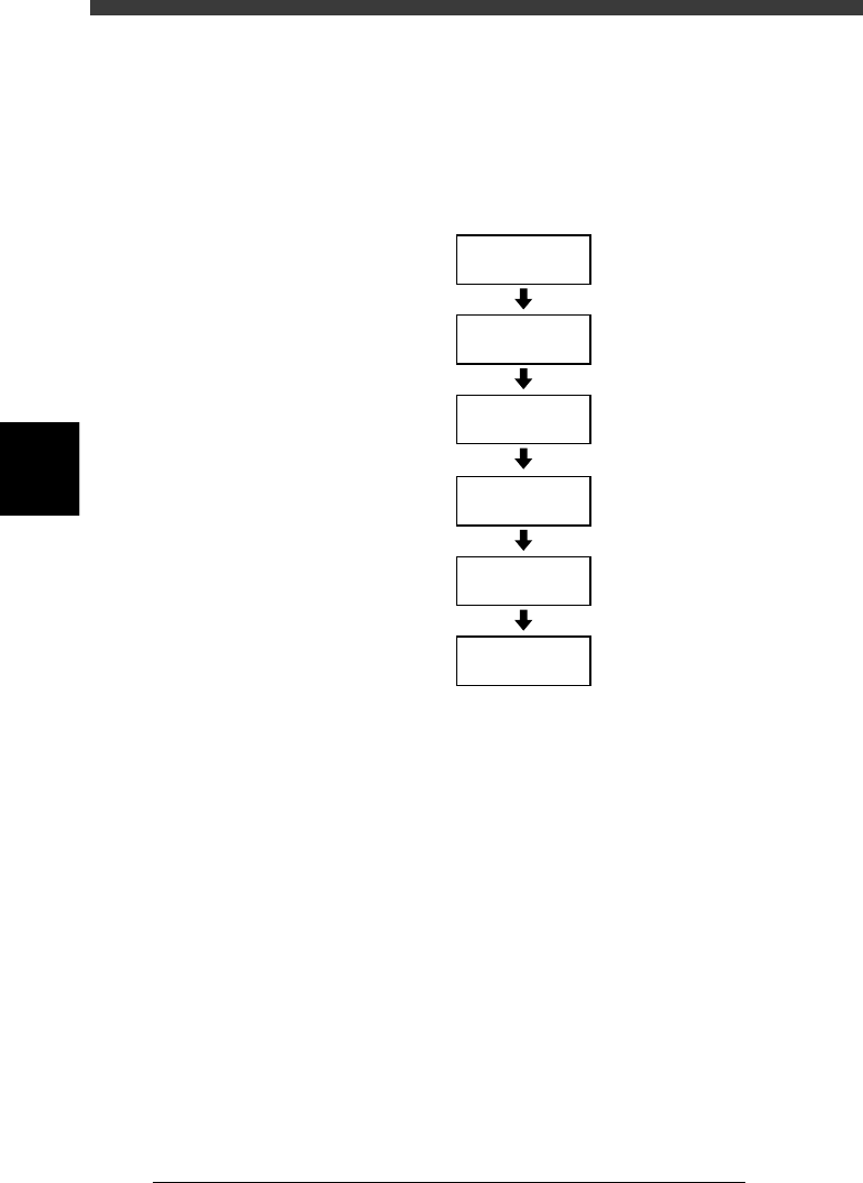
Basic operation flow chart
23403-C0-00
Servo-motor
ON
Safety check
Main power
supply ON
1/OPERATION/M
1/RUNNING
D2 INIT. SERVO ORIGIN
(Return to origin)
4
-7
EPD8013110
Operation
Chapter 4
4
Daily operation
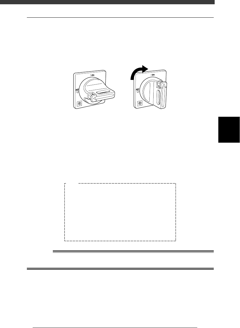
3.1 Turning the power ON
1
Turn the main power ON.
Turn on the main power switch at the front lower right of the machine, by
turning it to the right. The machine begins to load the program necessary
for machine operation.
Main power switch
21401-C0-00
ONOFF
2
Follow the instruction on the daily check items displayed
on the operation monitor.
The daily check items are displayed on the operation monitor after the
initial processing. Check each item as instructed and then press the
[ENTER] key. If maintenance is required, refer to Chapter 2 in the mounter
service manual.
Daily check items displayed on the operation monitor
27401-C0-00
E1045
<<Daily Examination>>
>NOZZLE TIP
>LEAF SPRING
>NOZZLE HOLDER
>LASER WINDOW
>CAMERA LENS
>FEEDER
>FEEDER PLATE
Please refer to the manuals in detail.
Ensure SAFETY and hit [ENTER] key.
<<Check>>
Break, Solder
Spring func.
Spring func.
Spring func.
Cleaning
Cleaning
Shutter
Cleaning
<<Predicted Error>>
Pick-up, Recognition
Pick-up, Comp. damage
Placement, Nozzle change
Pick-up, Comp. damage
Recognition
Recognition
Feeding, Pick-up
Placement, Pick-up
w
WARNING
BE SURE TO KEEP THE EMERGENCY STOP BUTTON PRESSED DURING
INSPECTION.