YV180X_Ope_E.pdf - 第225页
5 -149 EPD8013110 Operation Chapter 5 5 Creating the PCB data 2 Specify the copy destination. • T o copy to another line: Use the arrow keys to line up the cursor with the line you want to copy to. • T o copy into anothe…
5
-148
EPD8013110
Operation
Chapter 5
5
Creating the PCB data
13. Data editing for production PCB
13.1 Data editing
On a data editing screen, you can copy or move the specified data to
another line, another PCB data, and a static component data file. When
adding or deleting the data, you can insert or delete one or more lines, or
one or more columns as necessary. In addition, it is possible to copy and
delete the data registered in the database.
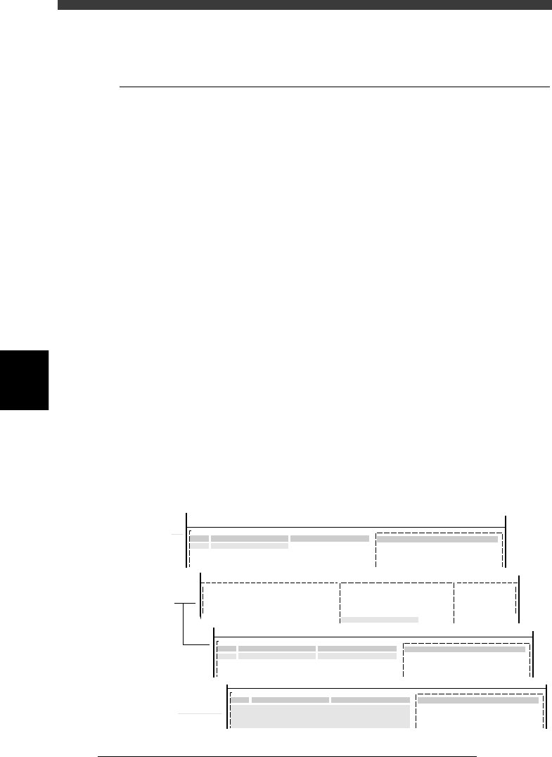
13.1.1 Copying the specified range
You can copy a specified range of data on the database screen or any
editing screen except the PCB Info. screen. To perform a copy, first select
the range of copy source data, then specify the copy destination. You can
copy the selected range between different types of PCB data or into the
database (user’s area).
1 Designate the copy source.
1. Use the arrow keys to place the cursor on the first data line to be
copied.
2. Press the [ESC] key to exit the current editing screen, then select <2/1/
C4 SELECT DATA> (<2/3/C4> in DATABASE mode) and press the
[ENTER] key. The selected top line will be highlighted on the screen.
3. Use the arrow keys to move the cursor through the last data line to be
copied.
4. Press the [ENTER] key to select the range. The selected range high-
lighted will slightly change.
Selecting the range
27568-C0-00
<<<APPLICATION>>> 2/DATA/M
<<MODE>> 1/EDIT_DATA
PCB :
OBJ :Component Info.
No.
1
2
3
COMPONENT NAME
R1608
R2125
R3216
COMMENT
1.BASIC INFO.
Database No.
Comp. Package
Feeder Type
:
:
:
Tape
8mmTape
501
<<MODE>> 1/EDIT_DATA
PCB :
OBJ :Component Info.
No.
1
2
3
COMPONENT NAME
R1608
R2125
R3216
COMMENT
1.BASIC INFO.
Database No.
Comp. Package
Feeder Type
:
:
:
Tape
8mmTape
501
PCB :
OBJ :Component Info.
No.
1
2
3
COMPONENT NAME
R1608
R2125
R3216
COMMENT
1.BASIC INFO.
Database No.
Comp. Package
Feeder Type
:
:
:
Tape
8mmTape
501
C/EDIT_TOOL
C4 SELECT DATA
1
2
3
R1608
R2125
R3216
Tape
8mmTape
501
<COMMAND_LIST>
Substep 1
Substep 2
Substep 3

5
-149
EPD8013110
Operation
Chapter 5
5
Creating the PCB data
2 Specify the copy destination.
• To copy to another line:
Use the arrow keys to line up the cursor with the line you want to copy
to.
• To copy into another PCB data file:
Press the [F2] key and select the PCB data into which you want to
copy. The information screen of the selected PCB data will be dis-
played, so line up the cursor with the line you want to copy to.
• To copy into the Static Component Information:
Press the [F2] key and select “STATIC_COMPONENTS_” to open the
Static Component Information screen. Use the arrow keys to line up the
cursor with the line you want to copy to. (This can be used only for the
component information.)
3 Copy the selected range.
1. Select <2/1/C6 COPY SELECTED LINES> and press the [ENTER] key.
(Select <2/3/C6> for the database.)
The “HOW TO COPY?” dialogue box then appears.
2. Select “INSERT” or “OVERWRITE” and press the [ENTER] key.
c
CAUTION
Note that selecting “INSERT” causes the data numbers after the insertion line to shift.
This may affect the PCB data in the static components and database. Likewise, the data
numbers will be shifted when component or fiducial mark data is copied.
4 Cancel the specified range.
Press the [ESC] key to exit the current editing screen, then select <2/1/C5
CANCEL SELECTION> and press the [ENTER] key. The highlighting
disappears.
n
NOTE
With the above procedure, it is not possible to copy the data between DATABASE mode
and EDIT_DATA mode (Component Info. or Mark Info. screen). When you want to copy
into the database, run the <SET FROM DATABASE> command or a reverse of the <SET
FROM DATABASE> command. For more details, see “3. Creating the user database” in
Chapter 5.

5
-150
EPD8013110
Operation
Chapter 5
5
Creating the PCB data
13.1.2 Deleting the specified range
You can delete a specified range of data on the database screen or any
editing screen except the PCB information screen.
1 Designate the range to be deleted.
Refer to the procedure explained in step 1 in the preceding section,
“13.1.1 Copying the specified range”.
2 Perform deletion
1. Select <2/1/C7 DELETE SELECTED LINES> (or select <2/3/C7> in
DATABASE mode) and press the [ENTER] key.
The “HOW TO DELETE?” dialogue box then appears.
2. Select “DEL EMPTY LINES” or “CLEAR” and press the [ENTER] key.
“DEL EMPTY LINES”: Note that selecting “DEL EMPTY LINES”
causes the data numbers after the deleted lines
to move up. This may affect the PCB data in
the static components and database. Likewise,
the data numbers will be shifted when
component or fiducial mark data is deleted.
“CLEAR” : The deleted range remains as empty lines. The
data numbers will not be shifted by data
deletion.