YV180X_Ope_E.pdf - 第240页
6 -5 EPD8013110 Operation Chapter 6 6 Using various functions 2.1 Creating the block repeat data This section explains ho w to create the PCB data using the block repeat function. c CA UTION Always set block repeat data …
6
-4
EPD8013110
Operation
Chapter 6
6
Using various functions
2. Using the block repeat function
A multi-block PCB is a printed circuit board consisting of two or more
independent printed circuits of the same type. Each printed circuit on a
multi-block PCB is called a “block”. The block repeat function allows the
machine to repeat the same mounting operation in each block on a PCB,
based on the reference block data. This function therefore greatly saves the
time required for creating data on multi-block PCBs.
Block repeat function
23602-C0-00
With the block
repeat function, you
can create or change
the data on an entire multi-
block PCB, by simply
creating or editing the
reference block data.
Block
Multi-block PCB
6
-5
EPD8013110
Operation
Chapter 6
6
Using various functions
2.1 Creating the block repeat data
This section explains how to create the PCB data using the block repeat
function.
c
CAUTION
Always set block repeat data AFTER setting the PCB Origin in the PCB information but
BEFORE setting the mount information.
1 Register the PCB data.
As with normal PCBs, first register the PCB name and create the PCB data
as explained in Chapter 5. However, if you are going to enter the block
badmark coordinates by teaching, you can leave the “BLOCK Badmark”
position in the PCB information unspecified.
2 Open the Block Repeat Information screen.
On an edit screen in the <2/1/EDIT_DATA> mode, press the [F3] key to
display the edit object list, then select “Blk Repeat Info.” and press the
[ENTER] key.
3 Register the reference block repeat data.
The block closest to the machine origin is normally viewed as the
reference block. Enter this block data in the No. 1 line.
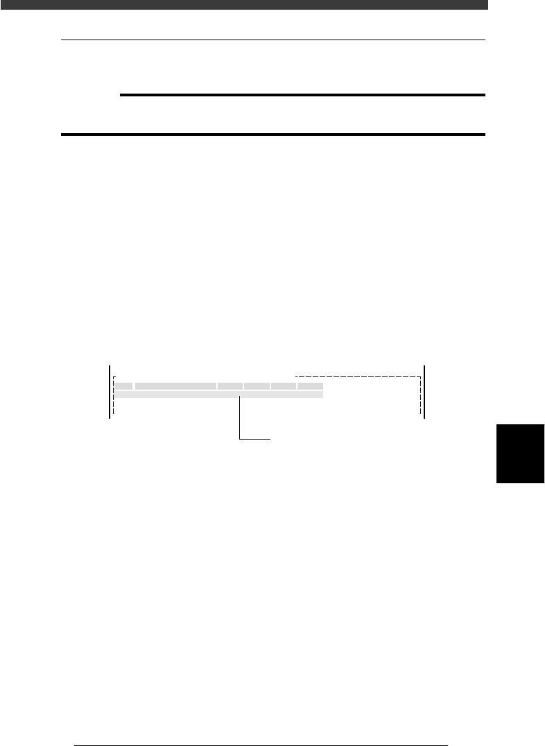
Block Repeat Information screen
27601-C0-00
No.
1
2
X Y Block Comment Skip? R
OBJ : Blk Repeat Info.PCB :
Enter the reference block repeat data
in this line.
1. Type any desired comment on the block in the Block Comment
column.
2. Enter the XY data on the reference block origin (hereafter called “block
repeat No.1”) relative to the PCB origin. Usually, the PCB origin is
specified at the same position as the block repeat No.1, so enter “0.00,
0.00” in the XY columns.
If the PCB origin is specified at a position other than the block repeat
No.1, enter the offset amount here.
6
-6
EPD8013110
Operation
Chapter 6
6
Using various functions
XY data
23603-C0-00
X
Y
Block repeat No.1
PCB origin
PCB origin is at a position
other than block repeat No.1
PCB origin is at the same
position as block repeat No.1
Reference
For details on the PCB origin, refer to “6. Creating the PCB information” in Chapter 5.
You can use teaching to enter the XY data. Refer to “12.2 Teaching” in Chapter 5 for the
teaching procedure.
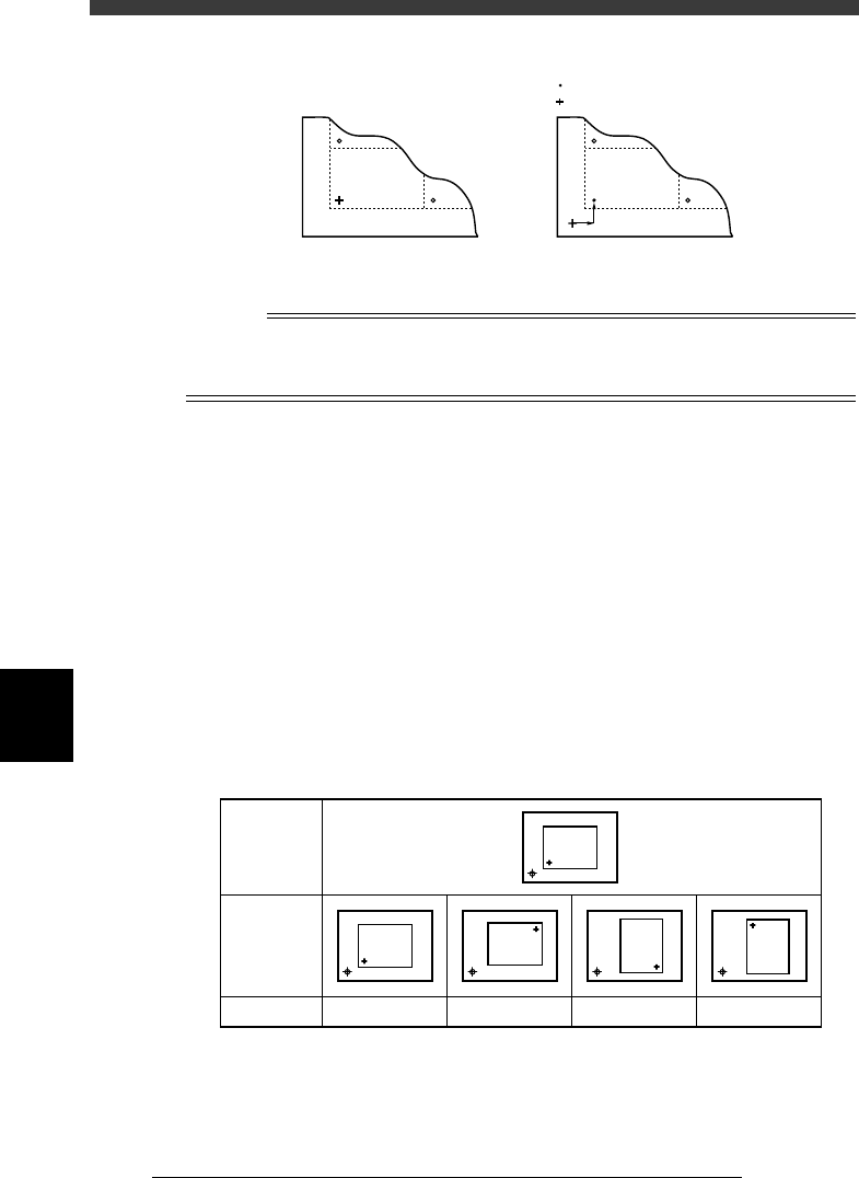
3. In the R column, enter the rotation angle of each block with respect to
the reference block. Be sure to enter “0.00” in the R column of the
reference block.
4. Set the “Skip?” column to “Exec” or “Skip”.
Set to “Exec” for the block on which you want to mount components,
and set to “Skip” when you do not want to mount.
4 Register the necessary data on all other blocks in the No.2
and lower lines.
1. Type a comment.
2. Enter the XY data on the origin of each block relative to the PCB origin.
You can also perform teaching input. (See “12.2” in Chapter 5.)
3. In the R column, enter the rotation angle of each block with respect to
the reference block.
Block repeat R data setting
25601-C0-00
Block
direction
R data
Reference
block
direction
Block
0 deg.
Block
Block
180 deg.
Block
90 deg.
Block
-90 deg.
4. Set the “Skip?” column to “Exec” or “Skip”.
Set to “Exec” for the block on which you want to mount components,
and set to “Skip” when you do not want to mount.