YV180X_Ope_E.pdf - 第44页
4 -5 EPD8013110 Operation Chapter 4 4 Daily operation 2. Inspection before operation The table below sho ws checkpoints you should make before turning the po wer ON. Pre-operation checks 25401-C0-00 Air Check that the bl…
4
-4
EPD8013110
Operation
Chapter 4
4
Daily operation
4
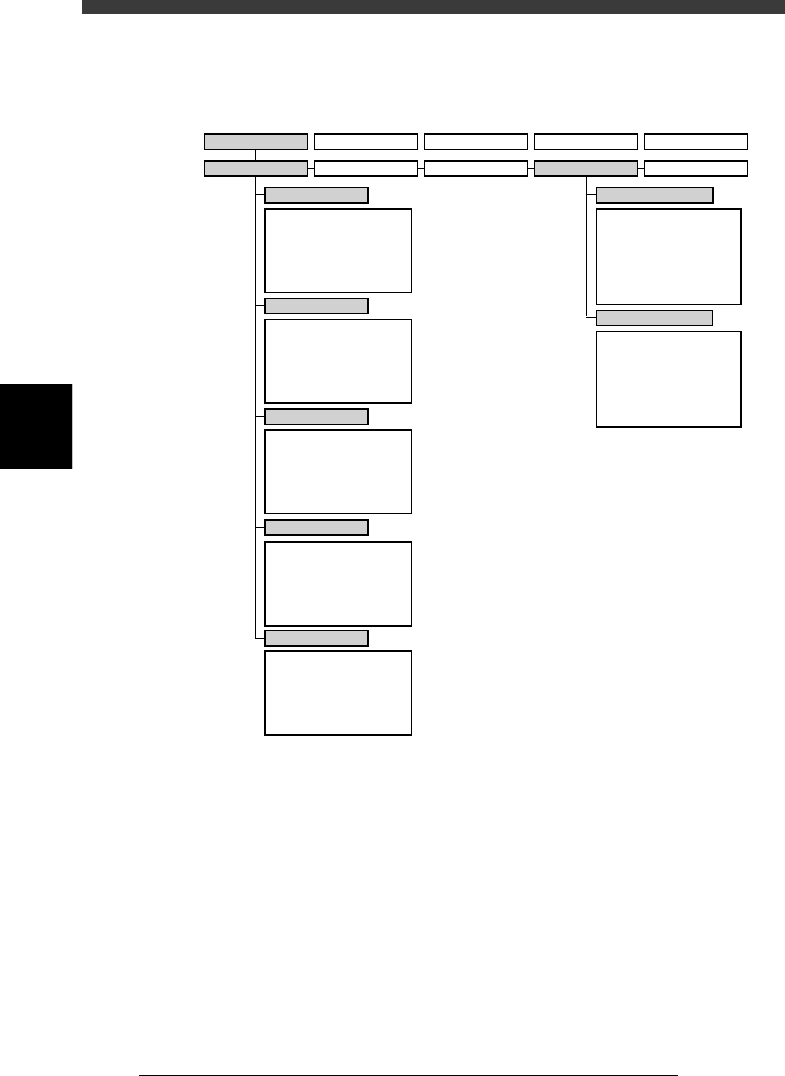
The following VIOS software modes and commands are used in this
chapter.
VIOS software modes and commands mainly used for routine operations
23402-D8-00
1/OPERATION/M 2/DATA/M 3/MAINTE/M 4/SHELL/M 0/EXIT
1/RUNNING
A/RUNNING
A1 STOP RUNNING
A2 AUTO RUNNING
A3 STEP RUNNING
A4 A_TABLE ON/OFF
A5 B_TABLE ON/OFF
A6 PCB TBL ON/OFF
B1
B2
B3
B4
B5
B6 RUNNING CONDITION
C1
AUTO RUNNING MONITOR
C2
C3
C4
C5
C6 SCROLL MONITOR
D1 WARM UP
D2 INIT.SERVO ORIGIN
D3
D4 ASSISTANT UTILITY
D5 STOPPING UTILITY
D6 RUNNING UTILITY
E1 DUMP & RESET
E2 RESET RUNNING
E3
E4 HALFWAY CONTINUE
E5 CYCLE STOP
E0 EXIT FROM RUNNING
B/CONDITION
C/MONITOR
D/INITIALIZE
E/SKIP&EXIT
A/IO UTILITY
A1
INPUT/OUTPUT MONITOR
A2
FEEDER OUT MONITOR
A3
A4 VACUUM IN MONITOR
A5 CHANGE NOZZLE
A6 ATS/YTF PALLET
A0 CONVEYOR UNITS
B1
SELECT SERVO MOTOR
B2 RUNNING SPEED
B3 POINT MOVE
B4
B5
B6 INIT.SERVO ORIGIN
B0 EXIT FROM MANUAL
B/SERVO_CONTROL
2/PRD.DATA 3/PRD.HISTORY 4/MANUAL 0/EXIT
4
-5
EPD8013110
Operation
Chapter 4
4
Daily operation
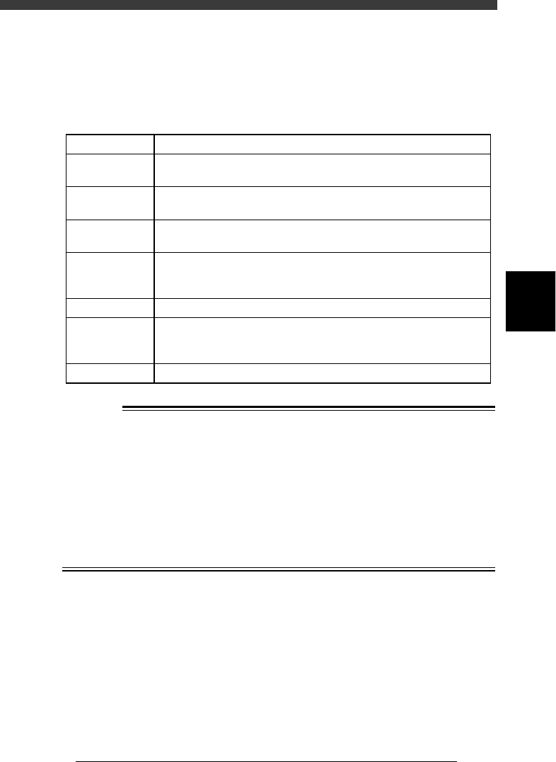
2. Inspection before operation
The table below shows checkpoints you should make before turning the
power ON.
Pre-operation checks
25401-C0-00
Air
Check that the black needle on the pressure meter reads
0.55MPa.
CheckpointItem
Check that the specified power supply is connected to the power supply
box located inside the lower left panel at the rear of the machine.
Check that emergency stop buttons are released.
Check that both front and rear covers are closed.
Check that each feeder is securely installed to the feeder plate and is not
floating.
Check that there is no foreign matter on the feeders.
Check that no foreign matter is on the conveyor.
Check that no parts of the conveyor unit interfere with each other
such as the push-up pins and conveyor rails.
Check that each nozzle is correctly installed to the head.
Power supply
Emergency stop
button
Safety cover
Feeder
Conveyor
Head
w
WARNING
THE WARNING LAMP IS THE IMPORTANT DEVICE THAT INDICATES THE
MACHINE STATUS. BEFORE BEGINNING ANY OPERATION, BE SURE TO
CHECK THAT THE WARNING LAMP SHOWS THE CORRECT MACHINE
STATUS AS FOLLOWS:
GREEN : THE MACHINE IS IN AUTOMATIC OPERATION.
YELLOW : AN ERROR OR INTERLOCK HAS OCCURRED.
RED : THE MACHINE IS IN EMERGENCY STOP.
NEVER ALLOW ANY PART OF THE BODY OR ANY OBJECT TO ENTER THE
MOVEMENT RANGE OF THE HEAD ASSEMBLY WHILE THE GREEN WARN-
ING LAMP IS LIT.
4
-6
EPD8013110
Operation
Chapter 4
4
Daily operation
4
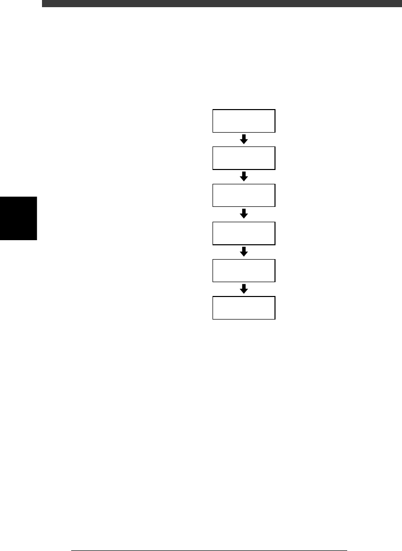
3. Starting the machine
This section describes the starting operations from power ON through
return-to-origin. You must perform the following operations before begin-
ning any work such as creation of new PCB data and PCB production.
Basic operation flow chart
23403-C0-00
Servo-motor
ON
Safety check
Main power
supply ON
1/OPERATION/M
1/RUNNING
D2 INIT. SERVO ORIGIN
(Return to origin)