Q170226E01.pdf - 第105页
RH5 SERVICE MANUAL 5.0−2 DA3SEC−83−000−A0 DA3SEC−83−000−A0 Sentence No. 5. MAINTENANCE GUIDE (MECHANICAL) This chapter includes explanations of how to check, adjust and repair when performing installation, inspection. x …

SERVICE MANUAL
RH5
5.0−1
5ダミー(Sectionのレベル1)
5.0ダミー(Sectionのレベル2)

RH5
SERVICE MANUAL
5.0−2
DA3SEC−83−000−A0
DA3SEC−83−000−A0
Sentence No.
5. MAINTENANCE GUIDE
(MECHANICAL)
This chapter includes explanations of how to check, adjust and repair when
performing installation, inspection.
x To avoid personal injury, correct procedure for performing maintenance must
be observed.
x Be sure to read “Safety Precautions” in this manual carefully.
x Refer to Operation Manual on how to operate the RH5.
x Tool and jigs mentioned in this chapter do not come with the RH5. Prepare them
in advance.
5.1 XY Table Positioner and Guide Rail Check and Adjustment
SERVICE MANUAL
RH5
5.1−1
DA3SEC−83−8H0−A0
5.1 XY Table Positioner and Guide Rail Check and
Adjustment
DA3SEC−83−8H0−A0
Sentence No.
When to perform
x After replacing the positioner
x When too much correction from the PC
board center towards the outside is
required while performing teaching (PC
board is tilted with respect to the X−Y
table).
x Micrometer
x Slotted screwdriver
x Lever−operated dial gauge
x Plastic tip hammerSteel rule
x Steel rule
Required tools
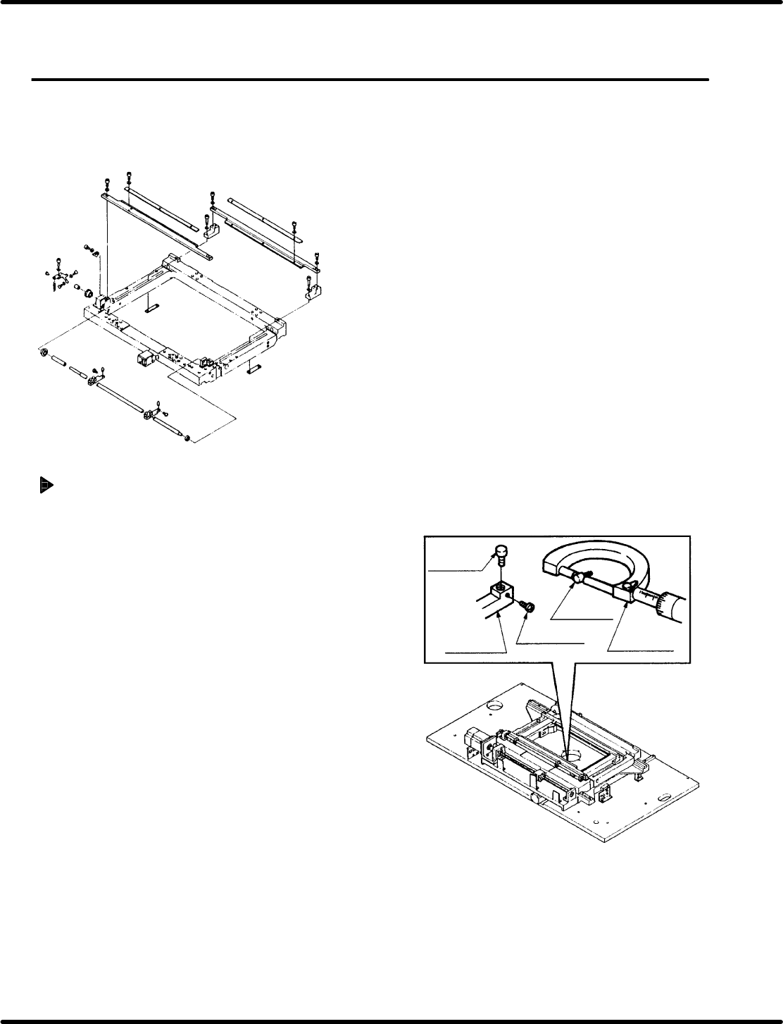
Positioner pin and shaft check
1. Loosen the lock screw and remove the pin
from the positioner lever. With the
micrometer, measure the diameter of the
pin. Here, check diameter is correct.
=REFERENCE=
If the positioner pin is too tight to be
removed, remove the entire lever and then
remove the pin with an pin extractor.
2. With the pin extracted, slide a PC board along
the rails checking to make sure it slides without
catching or incurring other irregularity.
3. Widen the distance between the X−Y table
guide rails to the with required for the largest
PC board. Attach the lever−operated dial gauge
to the upper frame and set the measuring
needle so that it contacts the shaft side of the
positioner. Slide the X−Y table in the X direction
checking shaft parallelism against the frame is
within 0.03 mm.
=REFERENCE=
If sliding the X− Y table by hand, make sure
the table does not slip in the Y direction.
Positioner
pin
Positioner
pin
Positioner
lever
Lock screw
Micrometer